PHOTOS
The build log in pictures. Every box opened, every part printed, every test run.
Take the picture while it is happening. You cannot go back and photograph it later.
Why photograph the build
Because the board is due in November and your memory is not evidence.
Before you put a tool down, take a picture of what you just did. It takes four seconds and it is the only chance you get.
Parts arriving
Every box, opened and checked in.
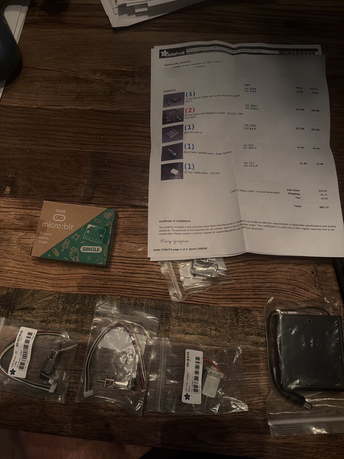
Checked against the packing slip: the micro:bit v2, two N20 gear motors, the roller lever whisker switch, and the 130 motor for the brush. All there. The 4 x AA battery pack came too. It was ordered before we switched to the power bank, so it goes in the Spares bag.
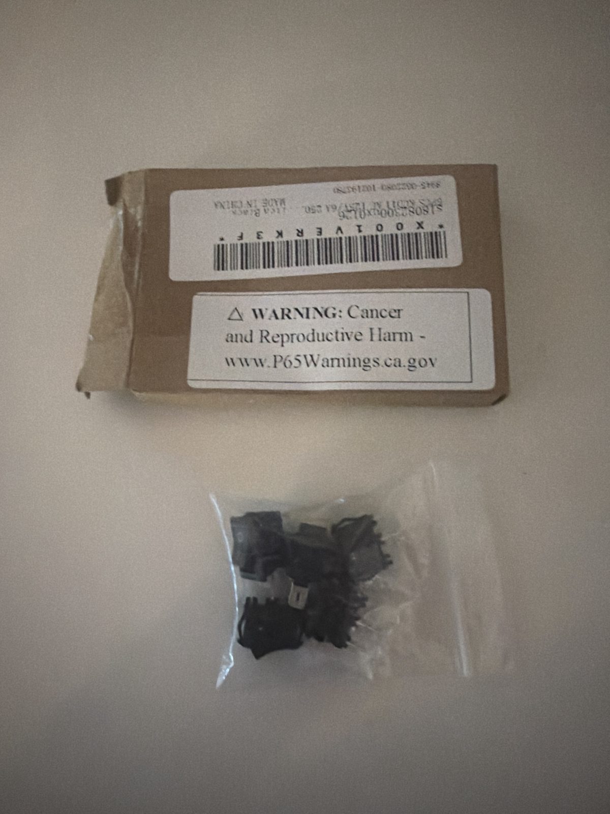
Five KCD11 on/off switches. Dusty needs two: one for main power and one for the brush motor. Three are spares.
- •The box with the packing slip next to it, before anything is unpacked
- •Each part still in its bag, so the part number shows
- •Anything wrong, broken or the wrong size, with the box in the picture
- •The whole kit laid out on the table before build day
Printing the chassis
The printer running, and the parts that come off it.
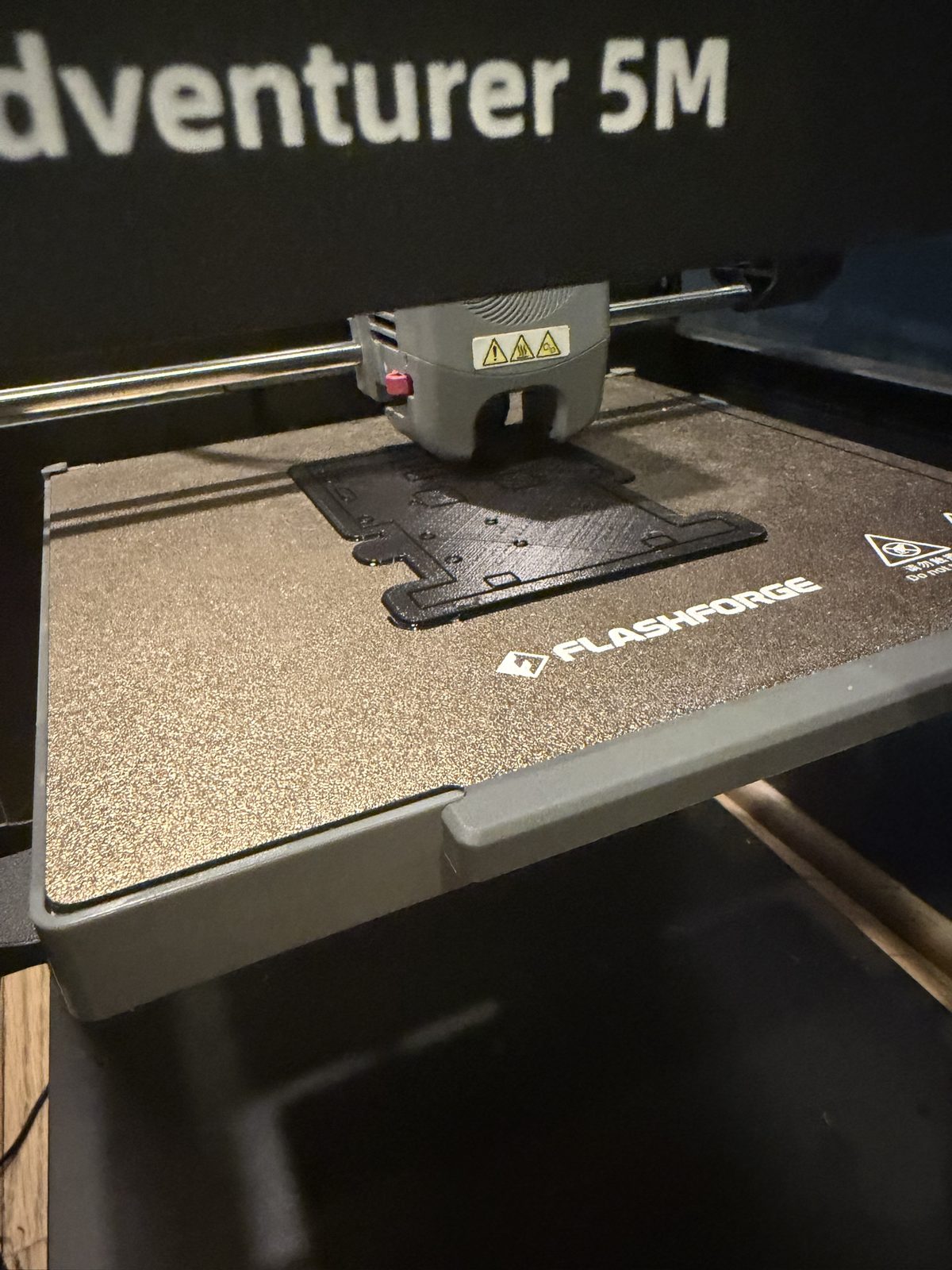
Close up of the first layers going down. Same base as before, plus the windows so the motors can sit flat.
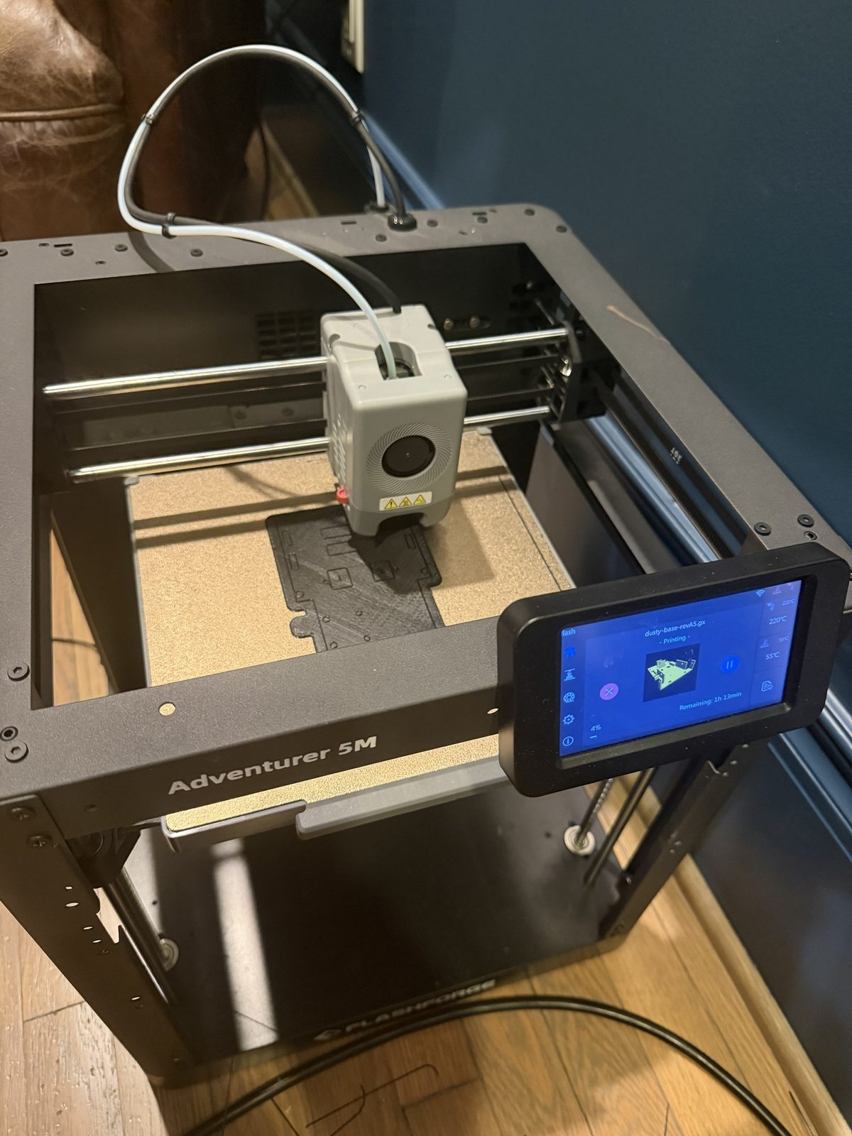
The new base after MOC-005, with a window for each motor plug. The screen says dusty-base-revA5, 4% done, 1 hour 13 minutes to go. Nozzle 220 C, bed 55 C.
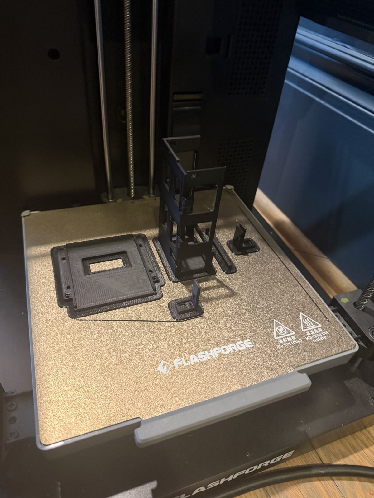
Batch 3 finished on the build plate: the deck with its square window on the left, the battery sleeve standing on its closed end in the middle with the thin keeper bar beside it, and the two sensor arms. The left arm is the one with the extra pad for the whisker switch.
- •The first layer going down
- •A part still stuck to the build plate
- •Support material being pulled off
- •A failed print, if one fails. Those go on the board too
Making it drive
Motors, wheels, caster, power.
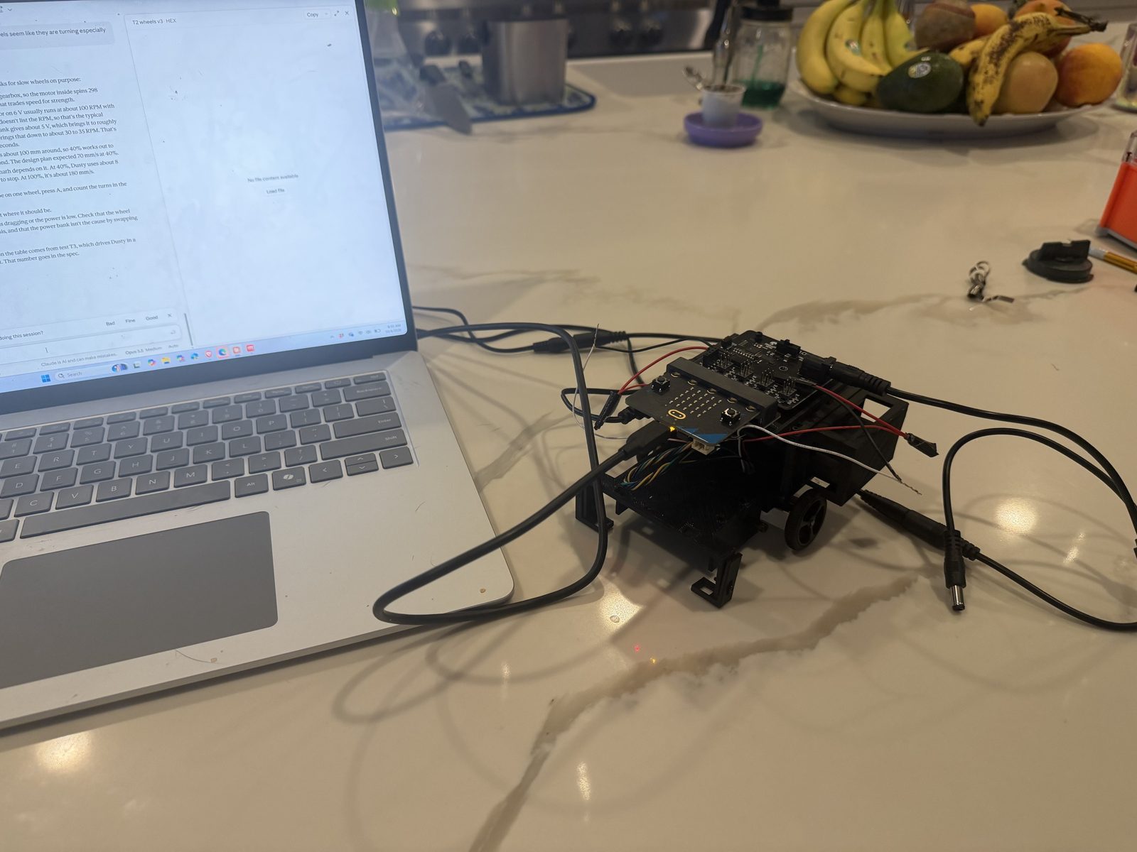
The micro:bit plugged into the laptop with a USB cable. It shows up as a drive called MICROBIT, and a new program is copied onto it as a .hex file. For driving tests the cable comes out and Dusty runs on the power bank.
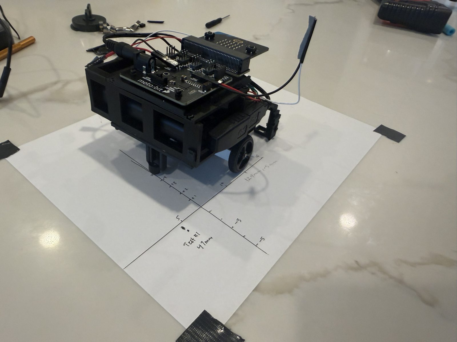
Speed and straight-line tests on one taped sheet of paper. The start is where the lines cross. Each run is marked with how far it went and how far it drifted: 47 mm in 5 seconds at 40% power, 124 mm and 5 mm drift at 70%.
Dusty on its own power bank with no cables, running the Spot Clean pattern: drive a row, turn, step over, turn back. Top speed is about 40 mm a second, the turns are tuned to 1.8 seconds for 90 degrees, and the starboard wheel runs at 97% so Dusty drives straight. No edge sensors yet, so this run was watched the whole time.
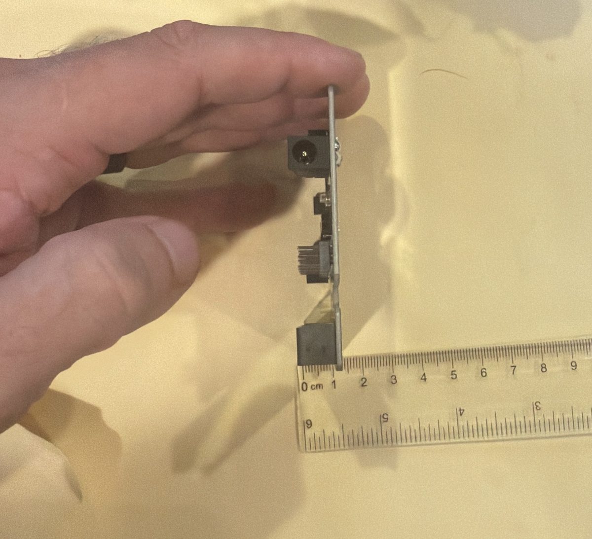
Side view to see how tall the parts on the board stand. The micro:bit slot and the power jack are the tallest, about 1.2 cm.
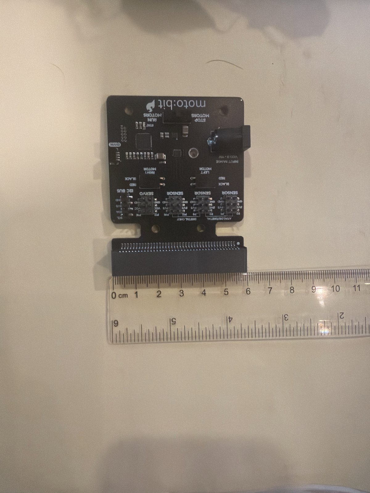
About 6 cm across the micro:bit slot. The model uses 62 mm, which is as close as we can read this ruler.
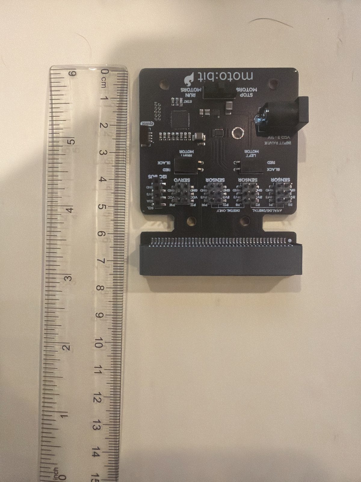
About 7.6 cm from the top edge to the bottom of the micro:bit slot. The 3D model uses 76 mm, so it matches.
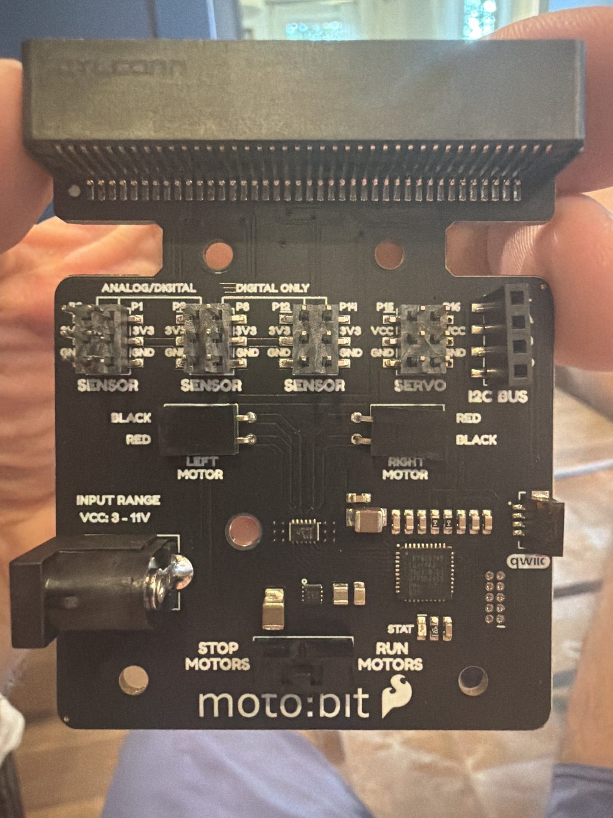
The motor board. The micro:bit plugs into the long black slot at the top. The two motor plugs are in the middle, the round power jack is on the left (3 to 11 volts), and the STOP / RUN switch at the bottom turns the motors on and off without unplugging anything.
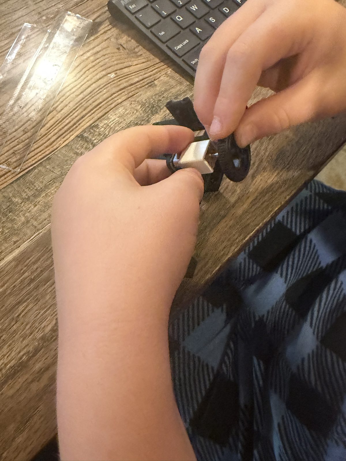
Nolan pushing a wheel onto the motor shaft, with the motor in its white bracket on the base.
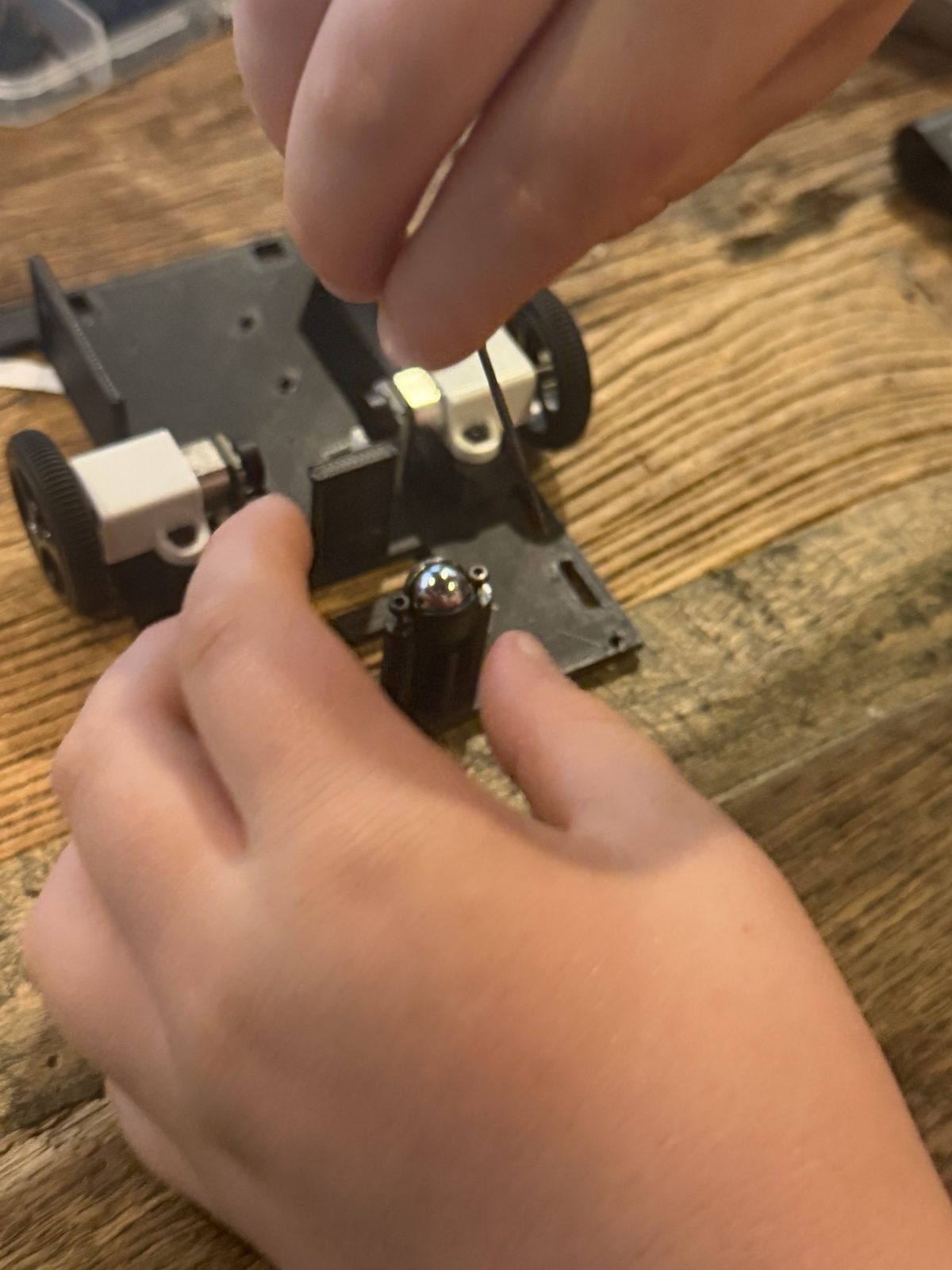
Nolan holding the ball caster on its post while the screws go in. The caster is the third wheel at the back that lets Dusty turn in place.
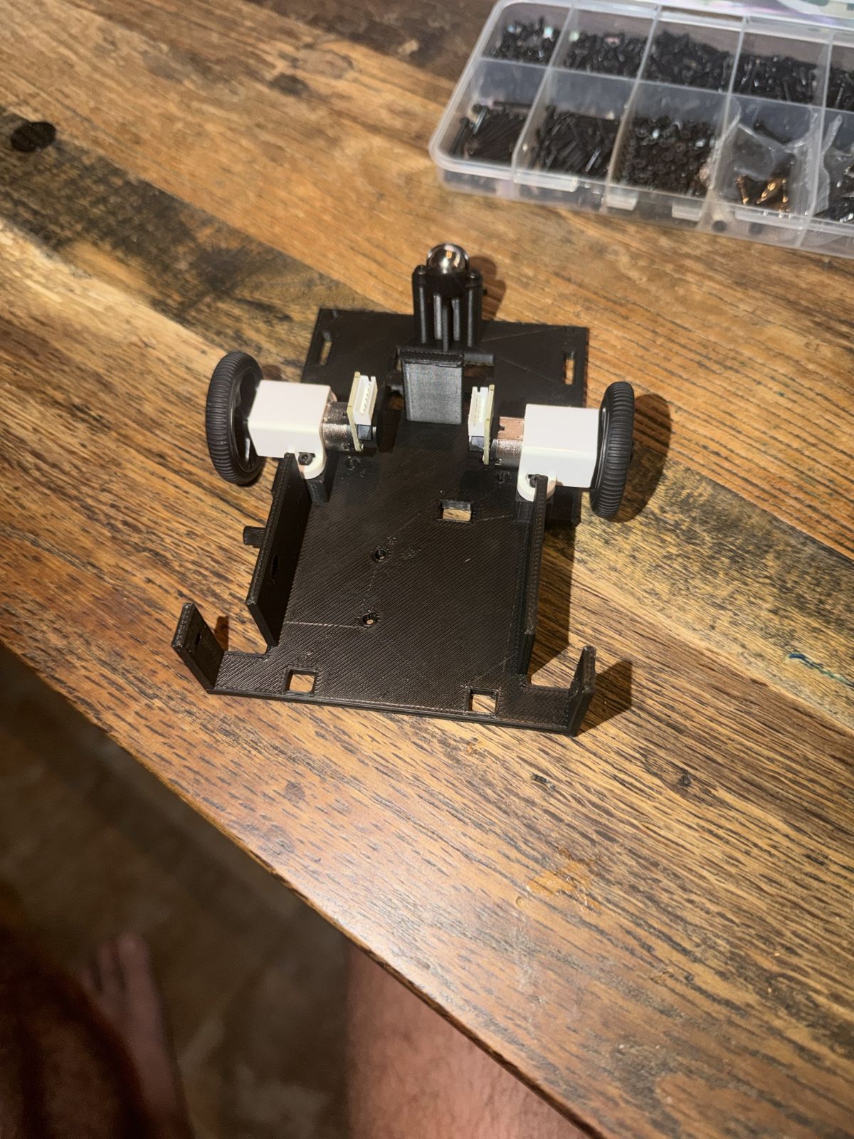
The base upside down, with both N20 motors, the wheels and the ball caster screwed on. The plugs on the back of the motors point down at the table, so the wires could drag. That has to be fixed before it drives.
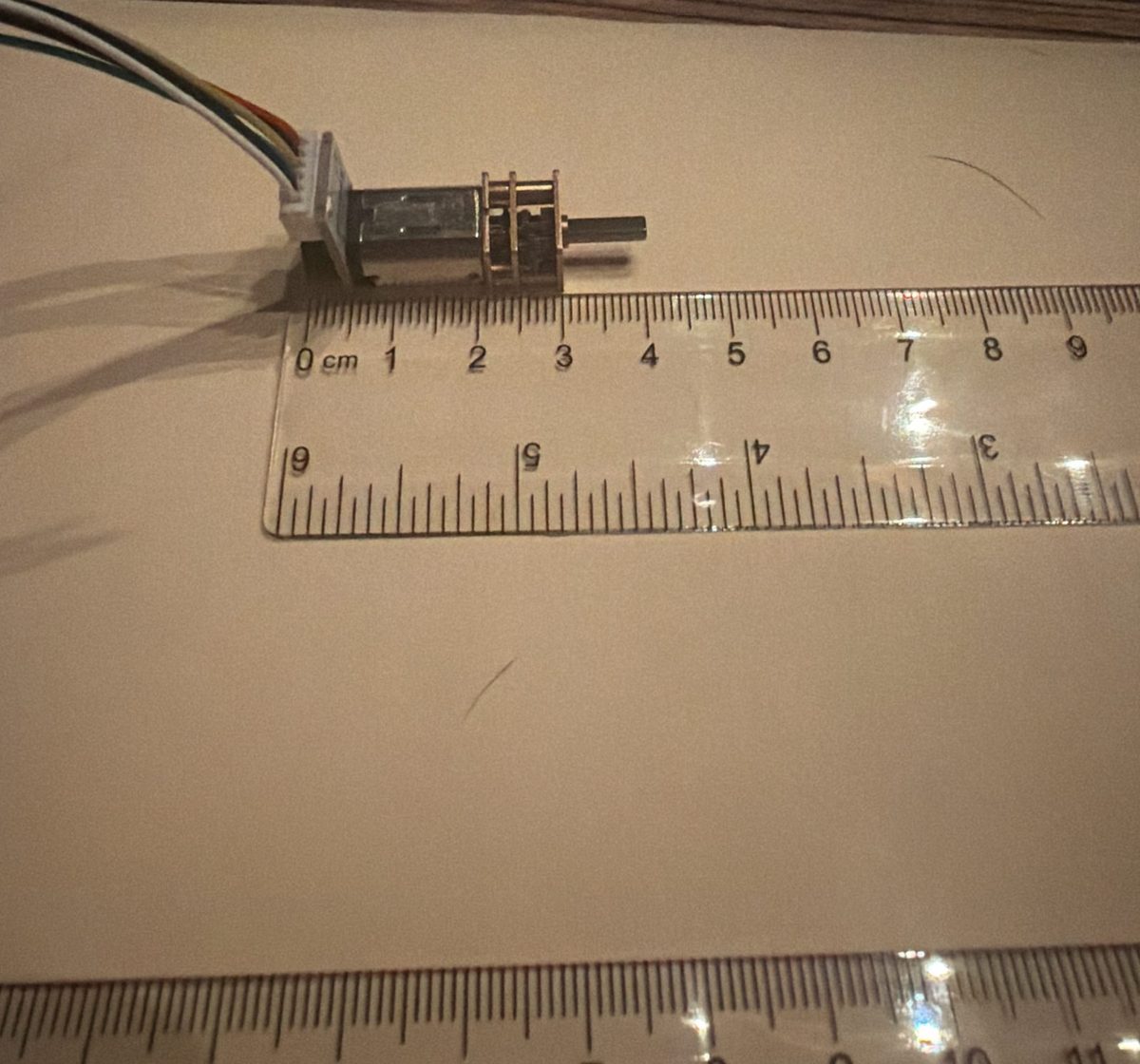
From the front of the gearbox to the back of the plug is about 33 mm. The model said 37 mm. The new base uses the number we measured.
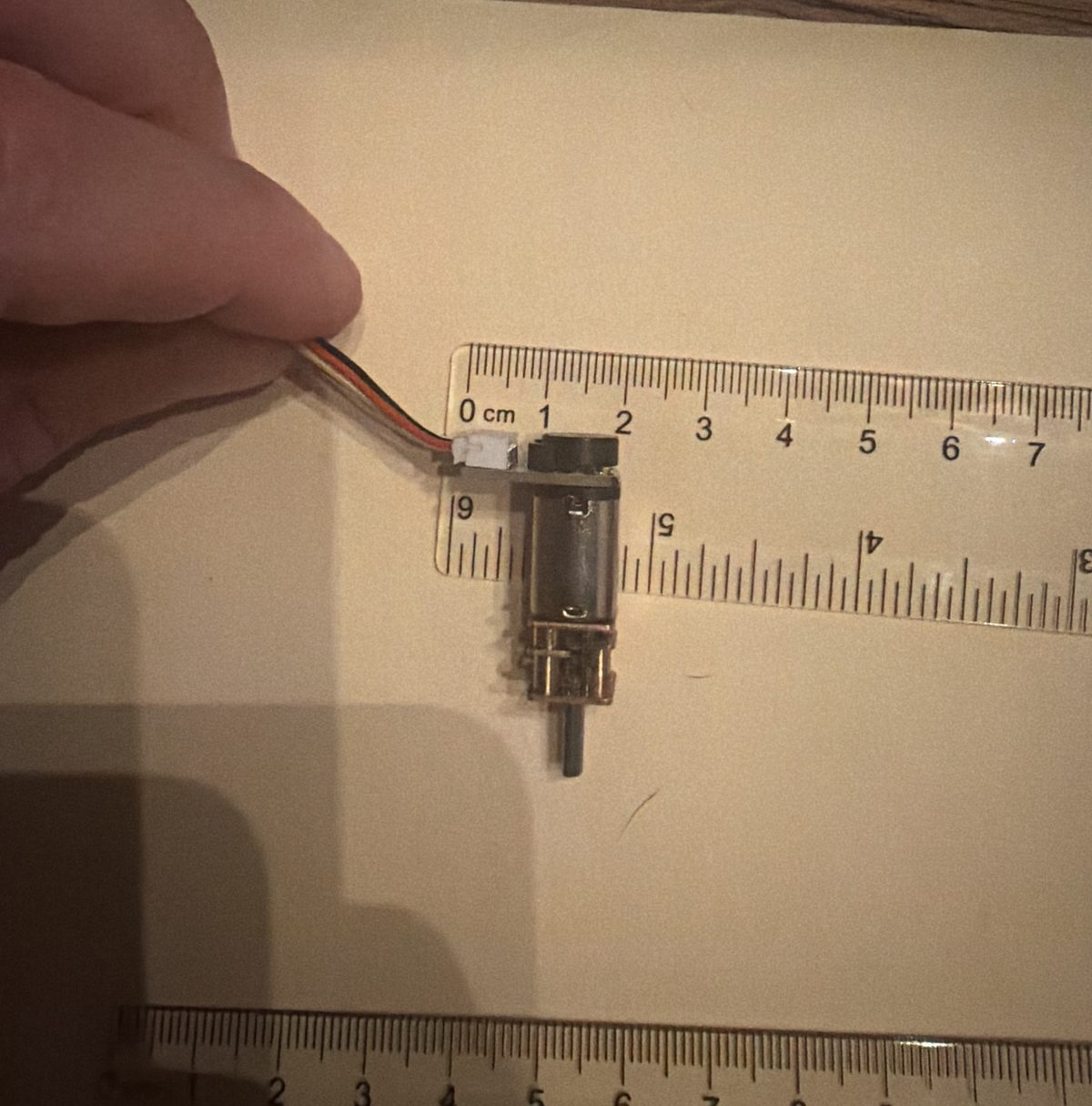
Ruler across the back of the motor to see how far the board and plug reach out to the side. About 16 mm from the middle of the motor. The base plate is only 14 mm away, so it does not fit.
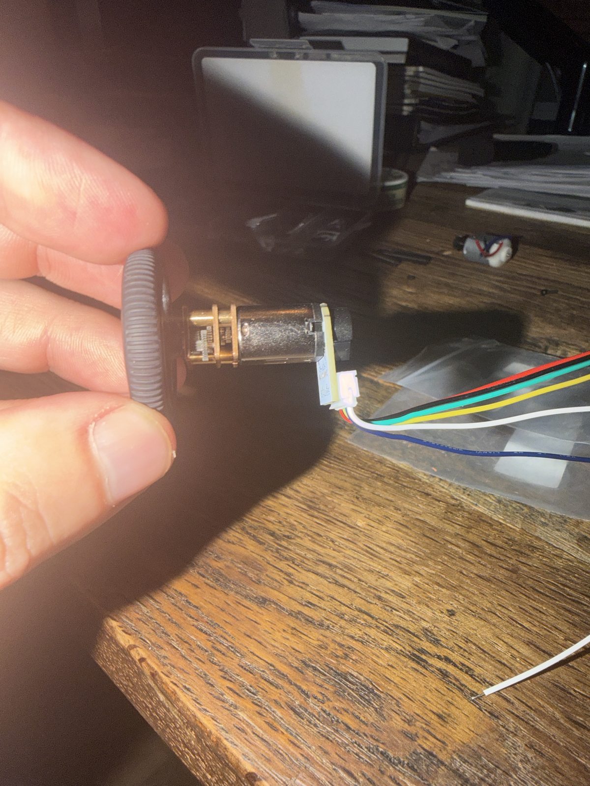
Wheel on, looking at the back of the motor. The encoder board and its white plug stick out to one side. Our 3D model had the motor the right length but left this part out.
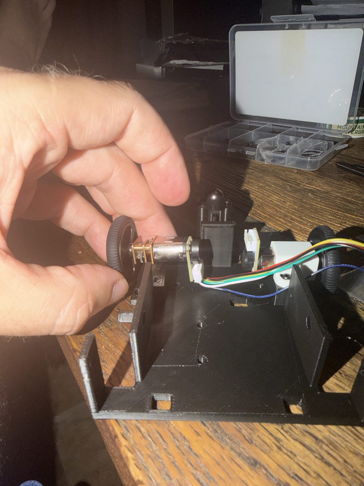
Trying a motor with its plug turned toward the base. The little encoder board on the back sticks out past the motor, so it hits the plate and the motor cannot sit down in its bracket. That is why the base got a window for each motor (MOC-005).
- •Motors and brackets held up next to the base plate before screwing them on
- •The wiring, close up, before the deck goes on
- •The first time the wheels turn
Cliff detection
The part the whole project is about.
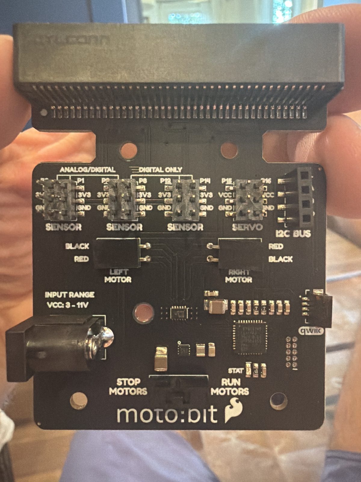
The SENSOR pins on the moto:bit. Each block is two columns of three pins. The left cliff sensor goes on the P0 column, the right cliff sensor on P1, and the whisker on P2. In every column the top pin is the signal, the middle is 3V3 and the bottom is ground. The SERVO block stays empty, because its middle pin is full battery power.
- •The sensor boom with a ruler against it, showing the 3 mm height
- •The micro:bit LEDs showing a sensor reading
- •Dusty stopped at the table edge, from the side, low down
- •The whisker switch touching the table
The sweeper
Brush, tray, and crumbs.
- •All three brush materials side by side before testing
- •The tray before and after a run, on the scale
- •A messy table, then the same table after
Experiment day
Four speeds, twenty runs each.
- •The test setup: table, tape marks, ruler
- •The data sheet part way through, with real numbers on it
- •A run at full power, where it is supposed to fail
The board and the fair
Putting it together and showing it off.
- •The trifold being laid out on the floor
- •The finished board
- •Nolan with Dusty at the showcase
Taking a better picture
Six things that turn a blurry phone snap into a board photo.
Dusty's pages are public, so anyone can see them. Keep addresses, order paperwork, phone numbers and faces of other people out of the shot. A packing slip is fine once the address part is folded under or cropped off.