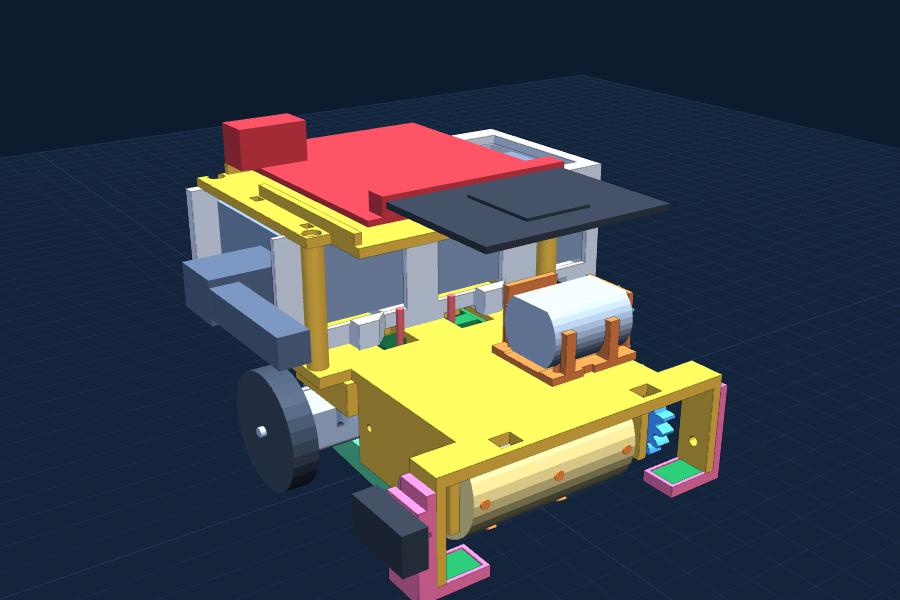
From a spool of plastic to a robot that sweeps the table and stops at the edge. Print a batch, clean it up, check it, then build what it unlocks.
Due Mon Nov 1621 printed pieces27 M2 screwsA little solderingCoded with Claude9 test programsRev A.7
Before anything
Start here
Safety rules
A grown-up runs the 3D printer.The nozzle is about 220°C and the bed about 60°C. Never touch either while it is printing or cooling.
Hands off while it prints.The printer moves fast and on its own, and this one has no door. Stand back and watch.
A grown-up does the soldering.The iron tip is hotter than the printer nozzle. Always put it back in its stand, and wash hands after touching solder.
Tiny screws and nuts are choking hazards.Keep them in cups, and away from little brothers.
Only use the cables from the parts list.A plug with the wrong voltage can cook the micro:bit.
Switch off before changing any wire.Every single time.
Never crush, pierce or drop the power bank.It is a lithium battery. If it gets hot, swells or smells, a grown-up takes it out and puts it somewhere safe.
Gears pinch and brushes grab.Brush switch off before your fingers go near the front.
Test on a low table first.A kitchen chair is a shorter drop than a counter.
Tools
3D printer
Grown-up runs it
Small screwdriver
Phillips #0 for M2
Needle-nose pliers
To hold the nuts
Soldering iron
Grown-up only
Ruler
Millimeters matter
Kitchen scale
To weigh crumbs
Laptop
Claude and MakeCode
Stopwatch
A phone works
The plan, weekend by weekend
NowPrint Batch 1, check the test pieces, then Batches 2 and 3. Code Lab setup and test T1 on the bare micro:bit while they print · Batches 1 to 3
Weekend 1Steps 2 to 5: motors, caster, deck and power. Tests T1 to T3: first drive and your real speed · Needs Batches 2 and 3
Weekend 2Steps 6 to 8: sensor arms and whisker. Tests T4 to T7: sensor numbers, loop timer, edge stop · Print Batches 4 and 5 during the week
Weekend 3Steps 9 and 10: brush, gears, tray, sweep test · Needs Batches 4 and 5
Weekend 4Step 11: tests T8 and T9, then the experiment · Charts for the board
After thatDisplay board, and practice explaining every wire and every line of the final program · Due Mon Nov 16
Before the first print
1Unbox everything that has arrived and check it against the parts list.
2Sort the M2 screws into three cups: 6 mm, 8 mm and 10 mm. Put the nuts in a fourth.
3Before Batch 3, measure the power bank and the 90 degree USB adapter with a ruler or calipers.The bank must fit inside 104 x 48 x 29 mm, and the adapter must stick out less than 28 mm. If anything is off, the sleeve gets fixed before it prints.
Know your gear
Meet the parts
Lay everything out before you build. These are the bought parts. Every printed part has its own card, next to a penny, in the batch that prints it.
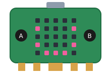
micro:bit v2
A tiny computer the size of a credit card cut in half. The 25 red squares are little lights called LEDs. The gold stripes at the bottom plug into other boards.
Job: Dusty's brain. It reads the sensors, decides what to do, and tells the motors to go.
Plugs in flat · LEDs face up
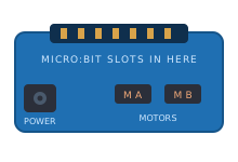
moto:bit motor board
A black board with a connector on its front edge for the micro:bit, a round hole for the power plug, connectors for two motors, a STOP/RUN motor switch, and rows of pins for sensors.
Job: The middleman. The micro:bit is far too weak to run motors, so it whispers instructions to this board, and this board does the heavy lifting.
3 to 11 volts · drives 2 motors
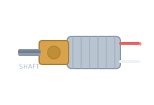
N20 gear motor ×2
A small silver can with a gold gearbox and a flat-sided metal shaft, in a black bracket. A tiny circuit board on the back, with a plug for a cable of six colored wires.
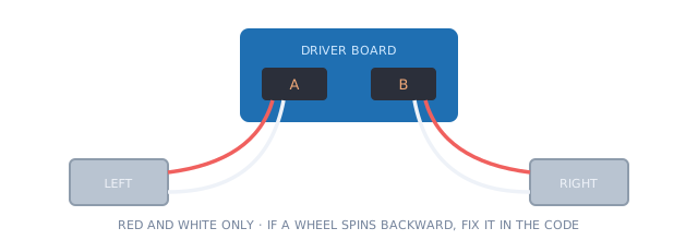
Job: One drives the left wheel, one the right. Only red and white power the motor. Blue and black power a turn counter on the little board, and yellow and green carry its signals. Dusty does not use the turn counter yet.
6 volts · 298:1 gearbox
Wheels ×2
Black wheels with a soft rubber tire. The hole in the middle is a circle with one flat side, shaped to match the motor shaft.
Job: Wheel size decides how fast Dusty drives, and speed is what the experiment measures. Do not swap for bigger ones.
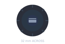
32 mm · press fit, no glue
Ball caster
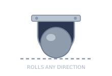
A little cage holding a 3/8 inch metal ball.
Job: The third foot at the back. The printed base already has the right height built in.
Two M2 × 8 screws
Cliff sensors ×2 (QTR-1A)
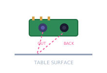
Two tiny bumps on a small board. One shines invisible infrared light down, the other watches for it to bounce back.
Job: The whole point of the robot. Light comes back means table. Nothing comes back means the table ended: stop now.
Mount exactly 3 mm above the table
Whisker switch
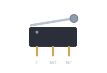
A small black block with a springy metal arm and a little wheel on the end. Push the arm and it clicks.
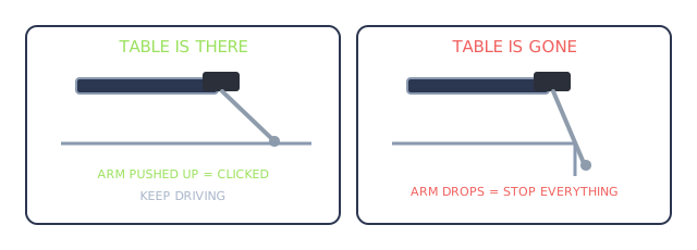
Job: The backup cliff sensor. The wheel rolls on the table and holds the arm in. Table ends, arm drops, switch clicks, motors stop.
3 tabs · use C and NO
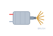
130 brush motor
A plain silver motor with two metal tabs and a thin shaft. It spins thousands of times a minute.
Job: Turns the brush roller through printed gears that slow it down and make it stronger.
Own on/off switch · geared down 5.4 times
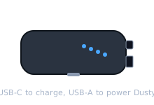
Power bank (Anker 321)
A rechargeable battery about the size of a candy bar, with a USB-C port, a USB-A port, a button and four blue lights.
Job: Powers everything and charges from a phone charger while it stays inside Dusty. It holds a steady 5 volts until it is empty.
5,200 mAh · charge before every session
Power cable and switch
A 90 degree USB adapter, a USB cable that ends in a round plug, an in-line on/off switch, and a short Y cable that turns one round plug into two.
Job: Carries power from the bank to the moto:bit and the brush motor, with a real OFF switch you can reach.
2.1 mm plugs · grown-up connects it
Rocker switch
A small on/off switch that snaps into the square hole on the brush motor mount.
Job: Turns the brush on and off without touching the code.
KCD11 size · 2 tabs
Pipe cleaners
Fuzzy craft wire.
Job: The bristles. Soft enough to bend, stiff enough to flick crumbs.
Cut to about 30 mm
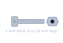
M2 screws and nuts
Tiny machine screws. M2 means the thread is 2 mm across. Three lengths: 6, 8 and 10 mm.
Job: They hold the motors, caster, deck, battery sleeve, gears and sensor arms. Most screw straight into holes in the plastic.
23 screws · 6 nuts · Phillips #0
PLA filament
A spool of plastic thread, 1.75 mm thick. The printer melts it and lays it down one thin line at a time.
Job: It becomes every printed part. PLA is made from plants like corn and sugarcane.
22 × 8 mm, 3 × 6 mm, 2 × 10 mm, plus 6 nuts. Spares get lost.
Every wire
Wiring map
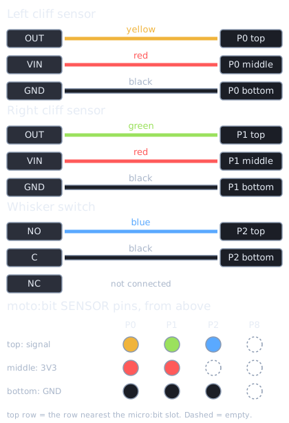
Every wire on Dusty, where it starts and where it plugs in. Stand behind Dusty and look down: the moto:bit in the picture is turned the same way as the real one.
The moto:bit, every connection
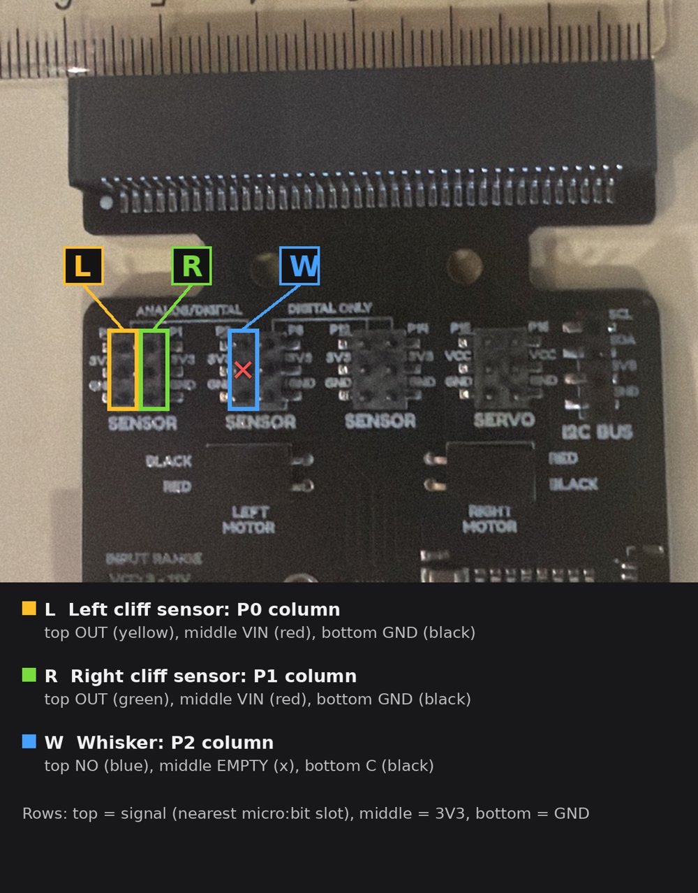
The sensor pins, up close
Each SENSOR header is two columns of three pins. Each column belongs to one micro:bit pin.
Where the power goes
Power bank
USB-A port, left side
→
90° USB adapter
points the cable forward
→
USB to barrel cable
Adafruit 2697
→
In-line switch
MAIN power, everything
→
Y splitter
one plug in, two out
Splitter end A
moto:bit barrel jack
Powers the micro:bit, the sensors, the whisker and both wheel motors.
Splitter end B
Screw-terminal jack → rocker switch → brush motor
The brush never goes through the moto:bit. It only needs on or off.
In-line switch(On the cable, taped to the deck edge)turns off: Everything: brain, wheels and brush.
STOP / RUN MOTORS(Back edge of the moto:bit)turns off: Only the two wheels. Brain stays on so you can test sensors with Dusty sitting still.
Rocker switch(Back of the brush motor mount)turns off: Only the brush.
Which pin the code reads
P0analog read pin P0· Left cliff sensor. Big number means no table under it.
P1analog read pin P1· Right cliff sensor.
P2digital read pin P2, with set pull pin P2 to up in on start· Whisker. 0 means the wheel is on the table. 1 means stop.
Motorsmoto:bit blocks: set LEFT / RIGHT motor· The micro:bit talks to the motor chip over two hidden wires (P19, P20). Nothing to plug in.
Wiring rules
Power off before touching any wire.Main in-line switch off, every time.
Sensors get 3V3, never VCC.The servo header’s middle row is VCC, the full power bank voltage. A sensor wired there sends 5 volts back into a micro:bit pin and can kill it. Stay on the three SENSOR headers.
Top row is the signal, bottom row is ground.Every column on the SENSOR headers is the same: signal at the top (toward the front), 3V3 in the middle, GND at the bottom.
Use a color for each job.Orange or red jumper for 3V3, black or gray for GND, a bright color for the signal. Then a wrong wire is easy to spot.
Black is not a motor wire on the N20.Only red and white go to the motor sockets. The other four stay taped.
Sounds can scramble the left sensor.In MakeCode the micro:bit also sends sound out of pin P0. If Dusty ever plays sounds, the left sensor reading will jump around. Keep sound blocks out of the cliff program.
A loose whisker wire stops Dusty.On purpose. If a whisker wire falls off, P2 reads 1 and Dusty stops, the safe way to fail.
Code Lab
Coding Dusty with Claude
You are the engineer. Claude writes the code. Your job is the part that matters: say exactly what Dusty must do, check what comes back, and prove it works with tests.
Rule for the whole project: you can explain every wire and every line. Judges will ask, "Did you write this?" Your answer: "I wrote the spec and the tests. Claude wrote the code. Ask me about any line."
1 Write the spec→2 Ask Claude→3 Read the answer→4 Flash it→5 Test it→6 Tell Claude what happenedthen back to 2 until it passes
Set up once: Claude, MakeCode and finding the micro:bit
1A grown-up signs in to Claude and makes a project called Dusty Code.Claude accounts are for grown-ups, so a grown-up stays next to you. You type the prompts.
2Download the starter spec, fill in the date, and add it to the project files. Add the moto:bit extension page too.Claude reads project files in every chat, so you do not paste them each time.
3Open makecode.microbit.org in Chrome or Edge. Start a New Project named Dusty T1 Hello.Name every project after its test. MakeCode keeps them, so you can always go back to one that worked.
4Add the moto:bit extension.Click Extensions at the bottom of the block list and search for moto:bit.
5Switch the editor from Blocks to JavaScript with the switch at the top.Claude writes JavaScript. Paste it in, then flip back to Blocks to see the same program as blocks.
6Find the device: plug the micro:bit into the laptop with the data cable.A drive called MICROBIT shows up in File Explorer. No drive means the cable only charges. Try another cable.
7Click Download. The first time, MakeCode asks to pair: Next, then Pair, then pick BBC micro:bit CMSIS-DAP and click Connect.After that, Download sends the code straight to the micro:bit. If pairing fails, Download saves a .hex file: drag it onto the MICROBIT drive. The yellow light on the back blinks while it copies.
8Unplug the cable before you switch Dusty on.The program stays on the micro:bit. Testing with no cable also proves Dusty works on its own.
The spec: Dusty’s instruction sheet for Claude
Claude has never seen Dusty. It does not know your left sensor is on P0, that black is not a motor wire, or that Dusty has 62 mm to stop. The spec file tells it. Every prompt starts with "Read dusty-spec.txt."
The starter has blanks for numbers only you can measure: your real speed, your sensor numbers, how fast your loop runs. Fill them in as the tests give them to you, change the version number, and swap the new file into the project.
Try it once: ask for T4 with no spec, then with the spec. Compare which pins Claude picks.
1One job per program.A test program checks one thing. The big program is built from small ones that already passed.
2Say what it must not do."No motors." "No sounds." Anything you leave out, Claude fills with a guess.
3Name the tools.MakeCode JavaScript, the moto:bit extension, the pins from the spec.
4Ask for an explanation.End with "Explain every line so a 4th grader gets it."
5Change one thing at a time.Two changes and it breaks, and you will not know which one did it.
Too vague
make dusty not fall off the table
Which pins? Which speed? What counts as the edge? Claude has to guess all of it, and a guess that looks right is the most dangerous kind.
Exact
Read dusty-spec.txt. Write test program T4 Sensor Numbers in MakeCode JavaScript. No motors, no sounds. Button A shows the left sensor number, button B shows the right. Explain every line so a 4th grader gets it.
Read it before you flash it
1Flip to Blocks. Does it look like what you asked for?
2Find the forever loop and every pause.Anything slow inside forever makes Dusty late at the edge.
3Find the numbers.Speeds, times, thresholds, pins. Do they match the spec?
4Point at every block and say what it does.Stuck on one? Ask Claude "What does this line do?" Still cannot explain it? Do not flash it.
Design the test first
Before you press Download, write three things in the notebook: what should happen, how you will measure it, and what counts as a pass. Then run it and write what actually happened. The tests are yours, not Claude’s. They are how you know the code is right.
When it goes wrong, tell Claude
I ran T6. I expected: Dusty stops at the edge. What happened: it stopped on the black placemat in the middle of the table, 3 times out of 3. The LEDs showed a check mark at the start. Here is the code I ran: (paste it). What should I check first?
Say what really happened, not what you think is wrong. Then change one thing and run the same test again.
The test programs
Small programs, one job each, built in order. Each one is in the build step where you need it.
FlashForge Adventurer 5M, 0.4 mm nozzle, textured PEI plate
Software
Easiest: the .gcode is already sliced for the Adventurer 5M with every setting below. Put it on a USB stick or send it from FlashPrint. The .3mf opens in Flash Studio or OrcaSlicer to change settings.
Material
Flashforge Generic PLA profile: nozzle 220°C, bed 60°C
Layers
0.2 mm, 3 walls, 5 top and 4 bottom layers, 20% gyroid infill
Brim
5 mm, except none on the three gears and 8 mm on the tall roller
Speed
Normal, except plates 1 and 4 run slower for the small gears and the roller
Supports
Off. Nothing needs them.
Hole size
X-Y hole compensation 0. The holes are already drawn to fit this printer (change orders MOC-003 and MOC-004).
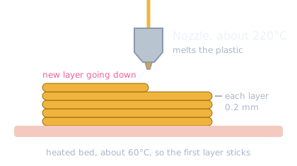
A 3D printer builds a part like a stack of very thin pancakes.
What is PLA? A plastic made from plants. The printer pushes the thread into a nozzle at about 220°C, where it melts like hot glue, and draws one layer 0.2 mm thick, then the next on top.
What is a brim? A thin flat ring around each part, like the brim of a hat, so corners do not curl up. Peel it off afterward.
PLA goes soft at about 60°C. A car in the Houston sun gets hotter than that. Never leave Dusty in the car.
1
Chapter 1
Batch 1: Fit check
First, before anything else · About 20 minutes · 4.3 g
1 · Print
On the plate
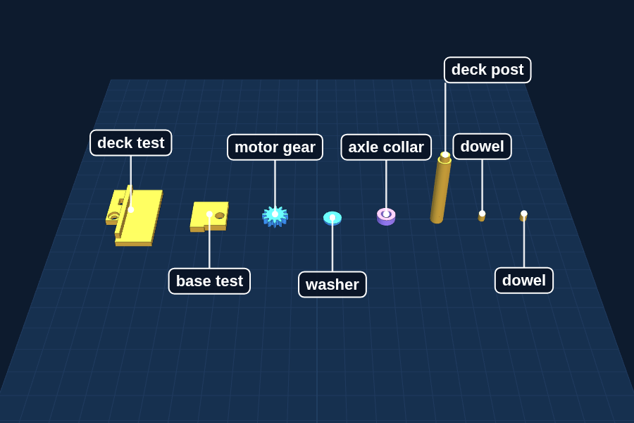
Motor gear, washer, axle collar, 2 dowels, 1 deck post, deck test piece, base test piece
Small parts, plus two test pieces cut from the real deck and base, that check whether this printer makes holes the right size. Finding out now takes 20 minutes. Finding out after the base or the deck takes hours.
1Watch the first layer go down. It should be flat and squished, not round like spaghetti.The first layer is the most important one. If it does not stick, nothing above it will.
2Each layer is 0.2 mm thick. The deck post is 35 mm tall. How many layers is that?Answer: 35 divided by 0.2 is 175 layers.
2 · Know your parts
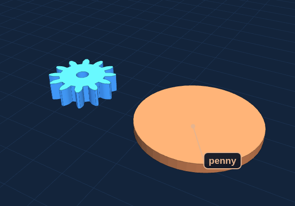
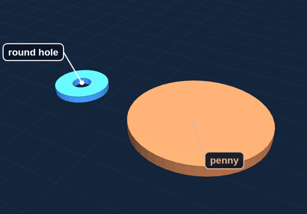
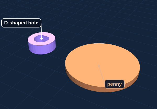
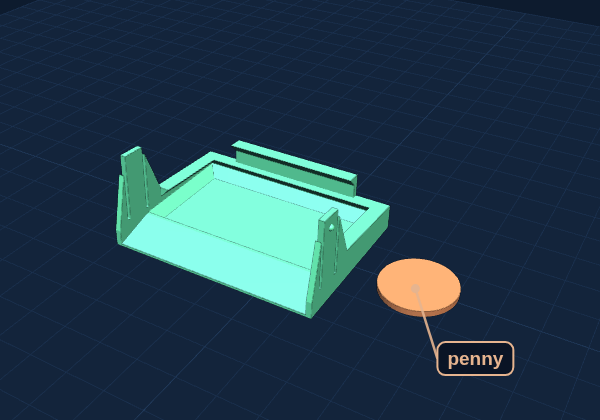
Every piece from this plate, next to a penny for size. The colors in the pictures only tell the parts apart: yours come out the color of your filament.
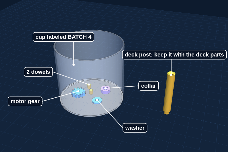
Motor gear
Small gear, 11 mm across and 3 mm thick. 12 teeth and a tiny round hole in the middle.
Job: Pushes onto the metal shaft of the brush motor and turns the big gear.
Goes to: BATCH 4 cup, after the test in step 2
Washer
Thin flat ring, 8 mm across and 1 mm thick. Round hole. The thinnest part on the plate.
Job: Sits on the end of the gear peg under a screw so the big gear cannot slide off.
Goes to: BATCH 4 cup
Axle collar
Thick ring, 8 mm across and 3 mm thick. The hole has one flat side, like a letter D.
Job: Slides onto the left end of the brush axle so the axle cannot slide out.
Goes to: BATCH 4 cup
Washer or collar? The collar is three times thicker and its hole has a flat side.
Dowels (2)
Two tiny pins, 3 mm across and 3.4 mm tall, about the size of a grain of rice.
Job: Hold the brush motor mount in exactly the right spot on the base.
Goes to: BATCH 4 cup
The easiest parts to lose. Put them in the cup first.
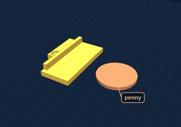
Deck test piece
Small flat corner, 21 × 33 mm, with one screw hole, a zip-tie slot and a raised rail. It is the front-left corner of the real deck.
Job: Tests the deck holes before printing the whole deck. The screw must slide through and the head must sit in the pocket.
Goes to: Keep it with the deck parts after the test
Only test pieces, not part of Dusty.
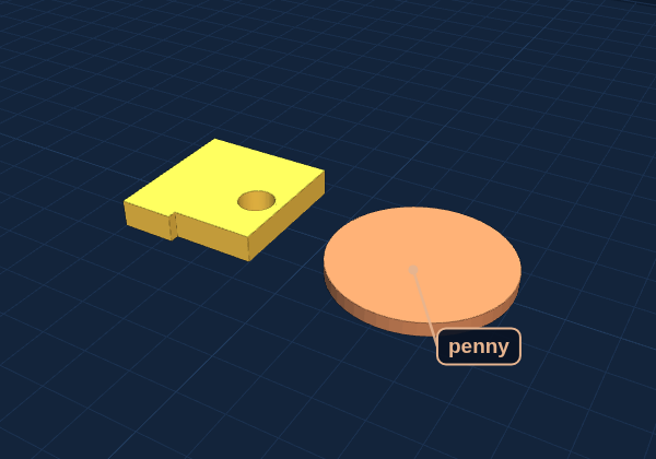
Base test piece
Small flat square, 15 × 16 mm, 3 mm thick, with one round hole. It is the patch of the real base where a deck post plugs in.
Job: Tests the post hole before printing the whole base. The skinny peg of a deck post must push in snug.
Goes to: Keep it with the deck parts after the test
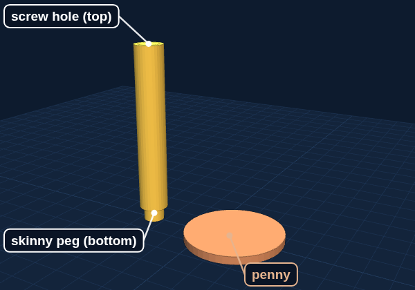
Deck post
Round stick, 35 mm long. One end has a skinny peg. The other end has a small screw hole with a funnel around it.
Job: Holds up the front of the deck. The peg goes down into the base, and a screw goes into the top.
Goes to: Keep it with the deck parts. Batch 2 prints the second post.
It prints standing peg up, so it comes off the printer upside down.
M2 × 8 screw
M2 means the screw is 2 mm thick. 8 means it is 8 mm long, measured from under the head to the tip. It is in the 8 mm cup.
130 brush motor
The silver motor with two metal tabs on the back and a thin metal shaft sticking out the front.
3 · Clean up and check
When it is done printing
1
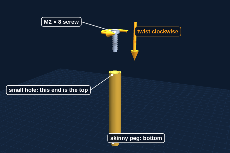
Find the deck post. The end with the funnel-shaped hole is the top. Twist an M2 × 8 screw into that hole, turning clockwise, about three turns.
Use a small Phillips screwdriver. Push down gently while you turn. Then check the result in the table below.
It bites and holds
The screw gets harder to turn and stays put when you let go.
Perfect. Change nothing.
It spins loose
The screw turns but never grips, or drops right in.
Holes print too big. A grown-up sets X-Y hole compensation to -0.05 in the printer software (Quality tab) and prints this plate again.
It will not start
Even pushing down, the screw will not go in.
Holes print too small. A grown-up sets X-Y hole compensation to +0.05 and prints this plate again.
Whatever number works, use it for every plate after this one.
2
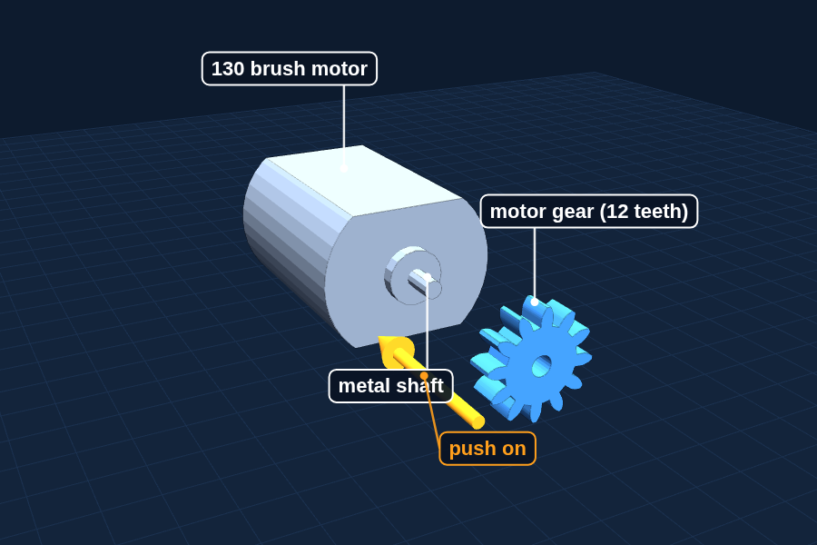
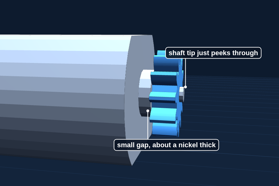
Push the motor gear onto the metal shaft of the 130 motor.
Set the back of the motor on the table and press the gear straight down with your thumb. Stop when the tip of the shaft just peeks through the gear, leaving a small gap between the gear and the motor. Then hold the gear and try to turn the shaft: the gear should not slip. A little loose is OK; a drop of superglue fixes it in Batch 4.
3
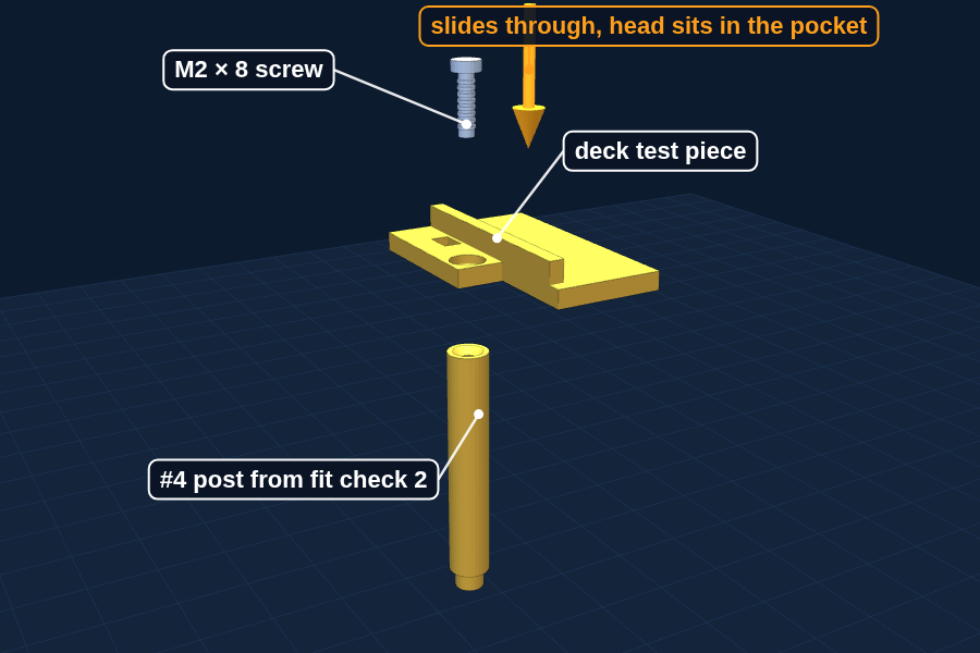
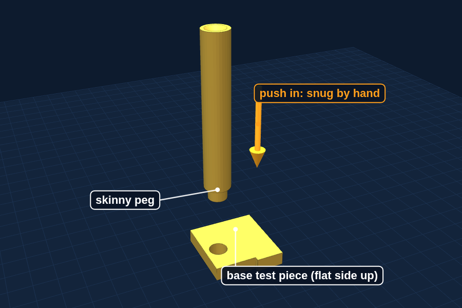
Test the deck and base holes with the two test pieces.
Deck test piece: set it on top of a deck post, screw hole over the post. Push an M2 × 8 screw through the hole and twist it into the post. The screw should slide through the test piece without threading, and its head should sit down inside the pocket. Base test piece: turn it flat side up and push the skinny peg of a deck post into the hole. It should go in snug by hand, not loose and not stuck.
Both fit
The screw slides through and sits in the pocket, and the peg pushes in snug.
The whole deck and base will fit. Print Batch 2.
Too tight
The screw has to thread through the deck piece, or the peg will not go in.
Stop before Batch 2. The hole needs to be drawn bigger: tell Dad which piece.
Too loose
The peg falls out, or the screw head drops through the pocket.
Stop before Batch 2. The hole needs to be drawn smaller: tell Dad which piece.
4
Put the motor gear, washer, collar and both dowels in a cup labeled BATCH 4. Keep the deck post with the deck parts.
Wiggle the gear back off the shaft first. It goes on for good in Build Step 9, after the motor is in its mount: with the gear on, the motor will not fit through the mount.
Ready to move on when
The screw bites, the gear is snug, the deck screw slides through and the post pegs in. Print Batch 2 with the same settings.
2
Chapter 2
Batch 2: Base plate
After Batch 1 passes · About 1 hour 20 minutes · 36 g
1 · Print
On the plate
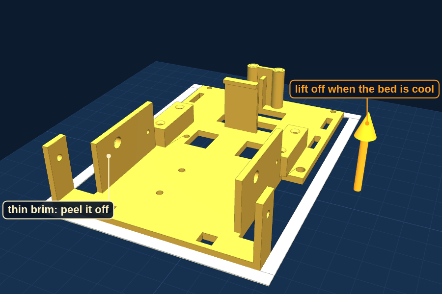
Base plate (upside down), 1 deck post, and a loose support block
The part everything else bolts to. It prints upside down so the top comes out perfectly flat.
1Code Lab setup, then test T1 on the bare micro:bit: Claude writes it, you read it, flash it and check it.Code is a list of steps the computer follows exactly, in order. Your job is saying exactly which steps, and proving they work.
2Read Steps 2 and 3 of the build guide so you know where the motors and caster go.
3Solder practice: a grown-up warms up the iron on a spare header pin.The sensors get soldered later, so practice now while nothing is at stake.
2 · Know your parts
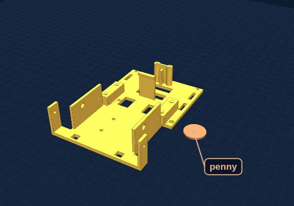
Every piece from this plate, next to a penny for size. The colors in the pictures only tell the parts apart: yours come out the color of your filament.
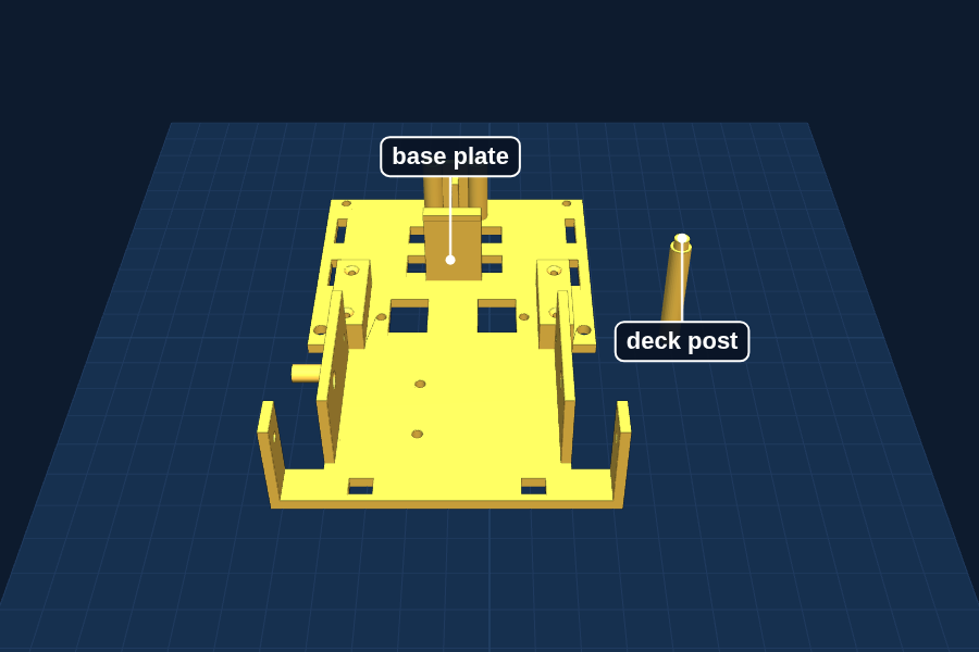
Base plate
The biggest part, 85 × 122 mm, with walls and posts sticking up and two square windows near the middle for the motor plugs. It prints upside down, so the flat side on the bed is the top of the robot.
Job: Everything bolts to it: the wheel motors, the caster, the brush, the sensors and the battery sleeve.
Goes to: Build Steps 2 and 3
Deck post (second one)
Same as the post from Batch 1: skinny peg on one end, tiny screw hole on the other.
Job: Holds up the front of the deck.
Goes to: Keep both posts with the deck parts
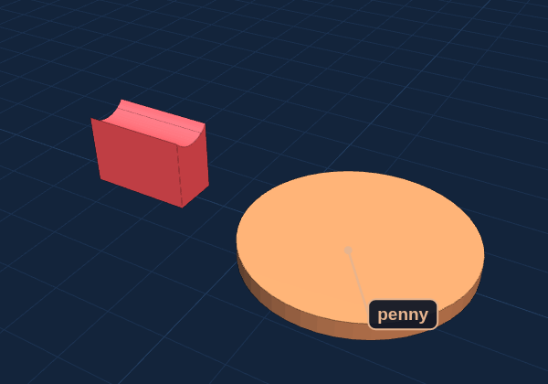
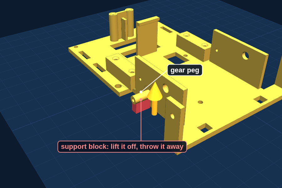
Support block
Small loose block, about 9 × 4 × 6 mm, standing just under the gear peg on the base.
Job: Only holds the peg up while it prints. It is not part of Dusty.
Goes to: Trash
3 · Clean up and check
When it is done printing
1
Wait for the bed to cool, then lift the base off and peel away the brim.
The brim is the thin one-layer sheet around the bottom edge. It peels off like tape. Cool plastic pops off by itself; warm plastic bends.
2
Lift off the small loose block that was standing under the gear peg, and throw it away.
It was only there to hold the peg up while it printed. Check the peg is round and smooth.
3
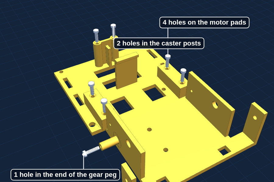
Run an M2 × 8 screw into each small pilot hole once, then back it out.
Four holes on the motor pads, two in the caster posts, one in the end of the gear peg. This cuts the threads now, so the real screws go in easily later. The four bigger holes for the battery sleeve are plain through-holes: skip them.
4
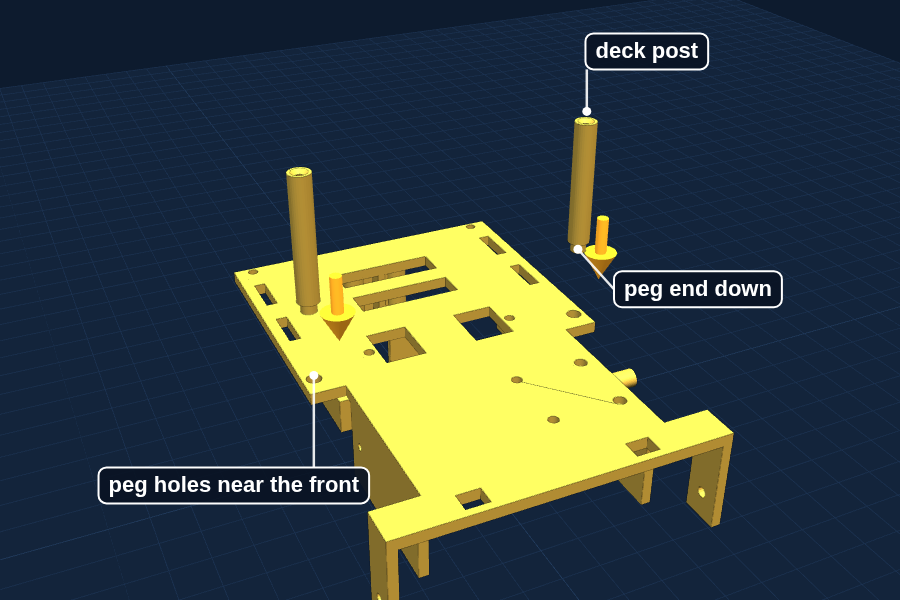
Push both deck posts, peg end down, into their holes near the front to check they fit. Then take them out again.
Ready to move on when
The base is clean and the posts fit. Print Batch 3.
4 · Build
This batch unlocks Steps 2 to 3.
2
Step 2: Mount the motors and wheels
About 45 minutes
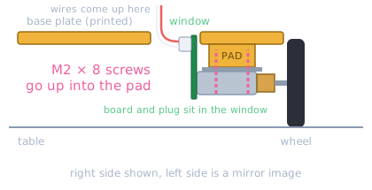
The two motors hang under the base on small printed pads. The pads put the wheels at exactly the right height, so there is nothing to measure. The little board on the back of each motor tucks up into a window in the base.
You need
Base plate (Batch 2)2 N20 motors in their brackets2 motor cables (six wires each)2 wheels4 × M2 × 8
Front view of the right side: the bracket screws up into a pad, and the little board and plug sit in the window.
a
Plug a cable into the back of each motor first.
The plug goes into the little board on the back of the motor. Once the motor is on the base, the plug is inside the window and hard to reach.
b
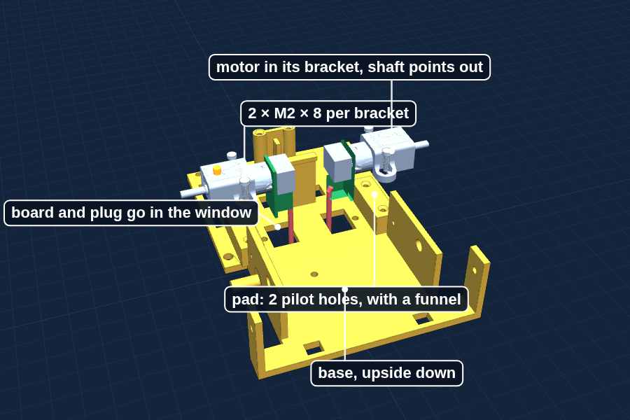
Slide each motor into a bracket, with the plug facing the same way as the flat side of the bracket where the screws go.
The gold gearbox goes into the bracket, the shaft sticks out the far side. The plug has to face the base.
c
Turn the base upside down. Find the two rectangular pads near the middle, and the square window just inside each pad.
Each pad has two small holes with a funnel around them. Those are pilot holes for the screws. The window is where the little board and plug go.
d
Feed the cable through the window, then hold the bracket on the pad with the shaft pointing outward and the plug pointing down into the window. Drive in two M2 × 8 screws.
The board and plug sit inside the window, so the motor sits flat on its pad. The funnel steers the screw in. Turn until snug, then stop: plastic threads strip if you keep going.
e
Do the other side the same way. Both shafts point out.
f
Pull each cable gently through its window so the wires come out on the top side of the base.
The wires leave the plug toward the middle of the robot and bend up along the inside edge of the window. Nothing hangs under the motors to drag on the table or catch crumbs. Do not pinch a wire under a bracket.
g
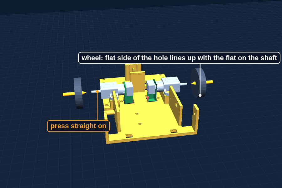
Push a wheel onto each shaft, flat side lined up with flat side.
Press straight on, thumb against the table. No glue.
Why it works
What does M2 mean?
Screws are named by how thick the thread is. M2 means 2 millimeters across, about as thick as a strand of spaghetti. M2 × 8 means 2 mm thick and 8 mm long.
The holes in the plastic are drawn 2.2 mm, but this printer makes small holes a little smaller, so they come out just under the screw size. As the screw turns, its thread cuts a matching groove in the plastic. That is called a self-tapping fit, and the small hole is a pilot hole. We found the right size with fit checks (change orders MOC-003 and MOC-004).
Why it works
Two kinds of gears in one robot
Inside the gold box on each drive motor is a stack of tiny metal gears. The motor spins very fast with almost no strength. The gears trade speed for strength: 298:1 means the motor turns 298 times for one turn of the wheel.
You will build a gear set like this yourself in Step 9, for the brush.
Why it works
Why are there windows in the base?
The little board and plug on the back of each motor stick out farther than the 3D model said. Pointing up, they hit the base, so the motor could not sit flat. Pointing down, the wires would drag on the table. We measured the motor with a ruler and cut a window in the base for each one (change order MOC-005).
Careful: Do not over-tighten. If a screw suddenly spins freely, the plastic thread is stripped. Stop and tell a grown-up. A slightly longer screw or a drop of glue fixes it.
You are done when
Both motors sit flat on their pads, both wheels spin freely, both shafts point outward, the wheels look parallel when you sight down the front, and each motor cable comes up through its window with nothing hanging underneath.
3
Step 3: Add the ball caster
About 10 minutes
The third foot. The printed posts are already exactly the right height.
You need
Ball caster2 × M2 × 8
a
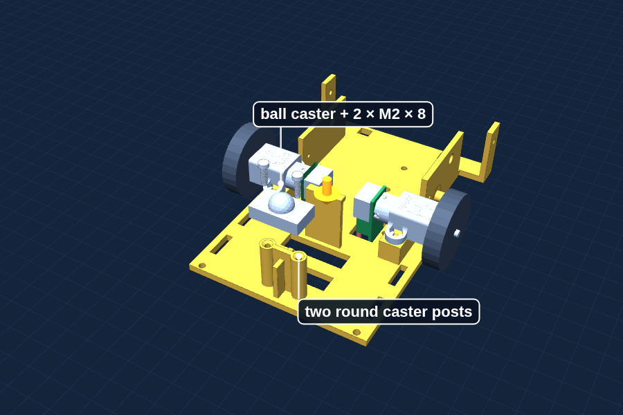
Keep the base upside down. Find the two round posts near the back.
They are exactly as tall as the caster needs, and each has a funnel hole.
b
Hold the caster on the posts and drive in two M2 × 8 screws.
Snug, then stop.
c
Turn Dusty right side up and set it on the table.
Why it works
Why three feet, not four?
Three points always sit flat, even on a bumpy table. That is why camera tripods have three legs. Four wheels would rock, and one would lift off whenever the table was not perfectly flat.
You are done when
Dusty sits on two wheels and the ball without rocking, and a gentle push sends it rolling straight.
3
Chapter 3
Batch 3: Deck, battery sleeve and sensor arms
After Batch 2 · About 1 hour 50 minutes · 42.7 g
1 · Print
On the plate
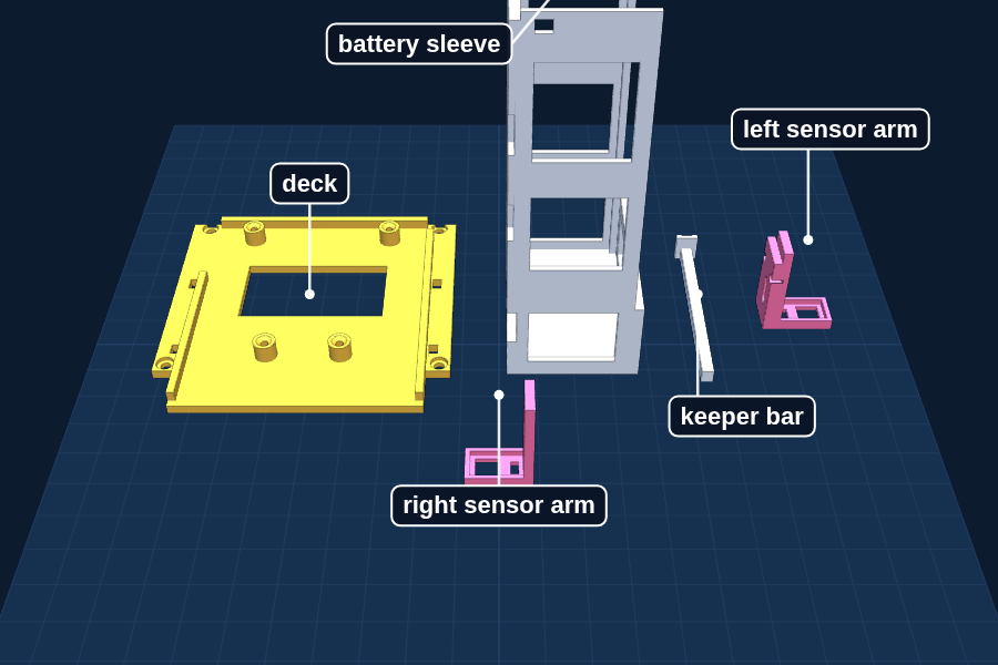
Deck, battery sleeve (standing on its end), keeper bar, right sensor arm, left sensor arm (the one with the switch pad)
The deck and the battery sleeve are needed for the first drive. The arms print now too, so the sensor weekend has nothing left to print.
1Plug the power bank into a USB-C charger and watch the four blue lights.Each light is about a quarter full. When all four stay on, it is charged.
2The bank holds 5,200 mAh. Dusty uses about 450 mA. Roughly how many hours is that?Answer: 5,200 divided by 450 is about 11, but the bank loses some energy changing its voltage, so plan on 6 to 7 hours.
3Put the motors and caster on the base (Steps 2 and 3) if those parts have arrived.
2 · Know your parts
Every piece from this plate, next to a penny for size. The colors in the pictures only tell the parts apart: yours come out the color of your filament.
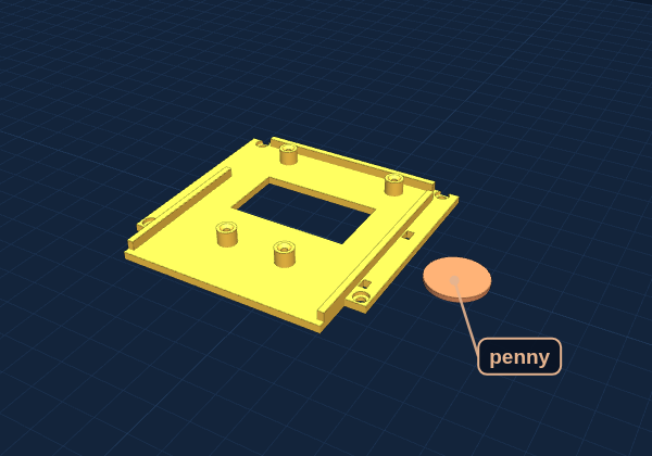
Deck
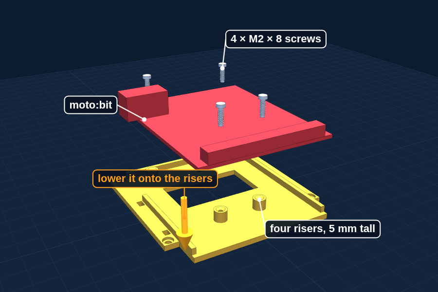
Flat shelf, 79 × 77 mm, with a square window in the middle, a raised guide along each side, and four round risers 5 mm tall with a screw hole in each.
Job: Holds the moto:bit board on top of the robot. The board screws onto the risers.
Goes to: Build Step 4
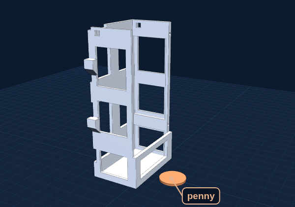
Battery sleeve
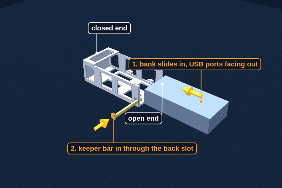
Long box, 106 mm, open at one end and closed at the other, with windows in the sides. It prints standing on its closed end.
Job: The power bank slides inside. The back of the deck rests on top of it.
Goes to: Build Step 4
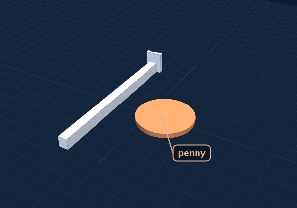
Keeper bar
Thin bar, 54 mm long, with a flat head on one end.
Job: Slides through the back wall of the sleeve so the power bank cannot slide out.
Goes to: Build Step 4
Right sensor arm
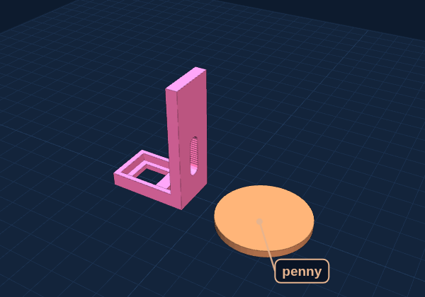
L shape, 27 mm tall, with a slot in the tall side and a small frame at the foot.
Job: Holds a cliff sensor face down just above the table.
Goes to: SENSORS cup, Build Step 6
Left sensor arm
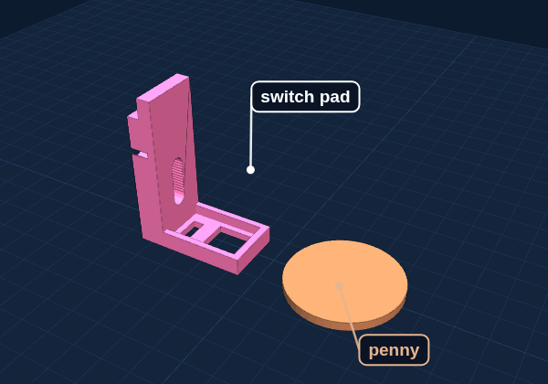
Same as the right arm, plus an extra pad with two holes on the outside.
Job: Holds the other cliff sensor. The pad holds the whisker switch.
Goes to: SENSORS cup, Build Steps 6 and 8
Right or left? Only the left arm has the pad with two holes.
3 · Clean up and check
When it is done printing
1
Clean up the deck, run an M2 × 8 screw into each of the four risers once and back it out, then set the moto:bit on the risers to check the fit.
This cuts the threads now so the real screws go in easily. All four board holes should sit right over the four risers.
2
Slide the power bank into the sleeve from the open end, USB ports facing out, all the way to the closed end. Then push the keeper bar in through the slot in the back wall until its head sits flat.
If the bank rattles, a grown-up adds a strip of foam tape to the floor rib.
3
Hold each sensor arm against its ear on the base and push an M2 × 8 screw through the slot.
Just a test fit. Take them off again and put both arms in a cup labeled SENSORS.
Ready to move on when
The moto:bit fits the deck and the bank fits the sleeve. That is everything for the first drive.
4 · Build
This batch unlocks Steps 4 to 8.
4
Step 4: Add the deck, the brain and the power
About 1 hour
The power bank rides in its own sleeve at the back, and the moto:bit and micro:bit sit on the deck above it. Keep the in-line switch OFF for this whole step.
You need
Battery sleeve, keeper bar, deck (Batch 3)2 deck postsPower bank, charged90° USB adapter, USB to round-plug cable, in-line switch, Y splittermoto:bit and micro:bitFoam tape12 × M2 × 8
a
Check that both motor cables already come up through the windows in the base.
The front of the sleeve sits over the back of each window. Once it is screwed down, you cannot feed a cable through anymore.
b
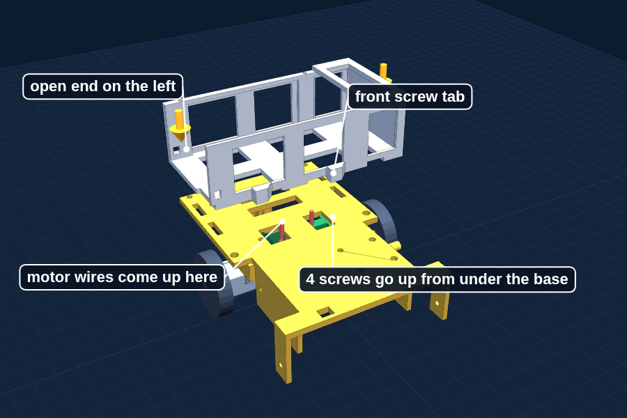
Set the battery sleeve on the back of the base, open end on the left, the two screw tabs toward the front.
The tabs and the back wall line up with four holes in the base. Keep the motor wires in front of the sleeve, not under it. The sleeve should sit flat without touching the little motor boards.
c
Turn the base over and drive four M2 × 8 screws up through the base into the sleeve.
Two into the front tabs, two into the back wall. The tray has to be out for this.
d
Stick a strip of foam tape along the rib in the middle of the sleeve floor.
Sticky side on the sleeve, never on the power bank.
e
Slide the charged power bank into the sleeve, ports facing out the left side, all the way to the closed end. Then push the keeper bar in through the slot in the back wall until its head sits flat.
The keeper crosses under the USB ports so the bank cannot slide out. Pull it out by the head when you need the bank out.
f
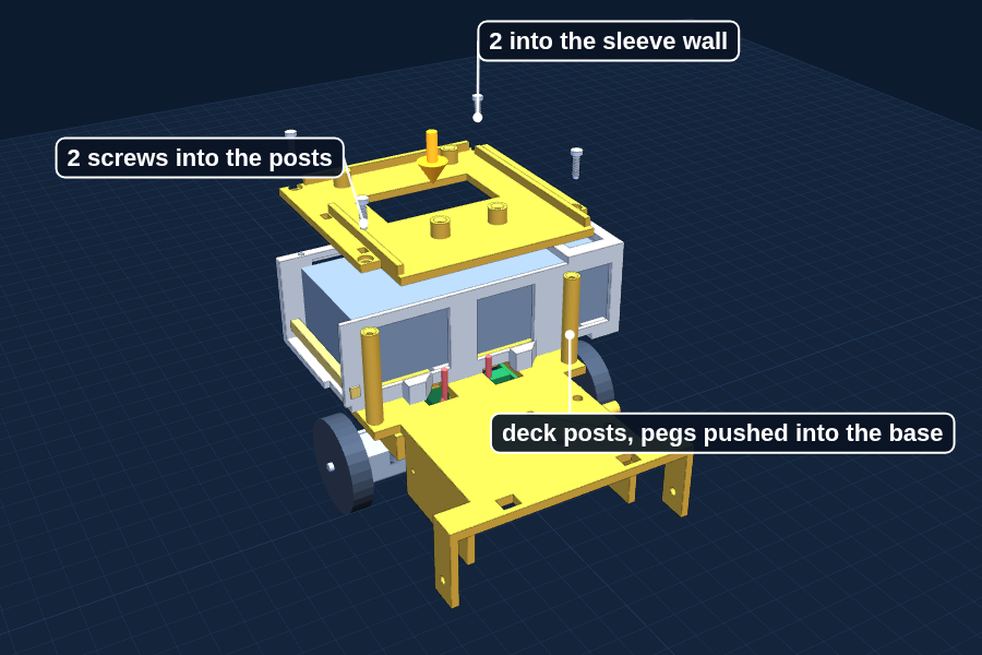
Push the two deck posts, peg end down, into the holes near the front of the base.
They go in snug by hand. The funnel end is the top.
g
Stick a second strip of foam tape under the deck, right over the bank.
It squeezes the bank gently so it cannot rattle.
h
Set the deck on the posts and the sleeve, and drive four M2 × 8 screws down.
Two into the posts, two into the back wall of the sleeve. The screw heads sit down in the pockets.
i
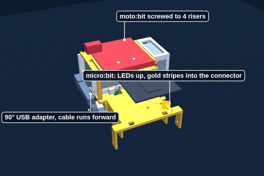
Set the moto:bit on the four round risers on the deck, connector edge toward the front, so the four holes in the board sit on top of the four risers.
Two risers are at the back corners and two at the narrow neck behind the connector. The board sits 5 mm up, so the solder bumps and pins underneath never touch the deck. The round power socket is on the left (change orders MOC-006 and MOC-007).
j
Drive an M2 × 8 screw down through each hole into its riser. Start all four, then tighten them a little at a time.
The risers have funnel pilot holes like the rest of Dusty. Snug, then stop: the board must not bend. No zip ties needed anymore.
k
Slide the micro:bit into the connector on the front of the moto:bit, LEDs and buttons facing up.
It lies flat and sticks out over the brush like a little roof. The gold stripes go in. If it will not go, flip it over rather than pushing harder.
l
A grown-up connects the power: the 90° adapter into the bank’s USB-A port, turned so the cable runs toward the front. Then the USB to round-plug cable, the in-line switch, and the Y splitter, with one end into the moto:bit.
Stick the switch to the edge of the deck with mounting tape where you can reach it. The second splitter end is for the brush motor in Step 9.
m
Flip the switch ON, then tap the button on the power bank once. The micro:bit should light up.
Nothing? Check every plug. Then check the bank is charged: pull the keeper bar, slide the bank out and press its button to see the lights.
n
Switch off and run test T1 below. It proves the laptop can find Dusty and put code on it.
Do the Code Lab setup first if you have not. Flash with the cable, unplug the cable, then switch Dusty on.
T1Test program: Hello, Dusty
Checks: The laptop can find the micro:bit and put code on it
1 · Write down first
What you will see at switch on, after pressing A, and after pressing B.
2 · Ask Claude
Read dusty-spec.txt. Write test program T1 Hello in MakeCode JavaScript. When Dusty switches on, scroll DUSTY once, then show a happy face. Button A shows a heart. Button B shows a check mark. No motors, no sounds. Explain every line.
3 · Read it, flash it, run it. It passes when
All three happen with the cable unplugged, running from the power bank. That proves the program lives on the micro:bit, not on the laptop.
Why it works
What even is a microcontroller?
A laptop can do millions of different things. A microcontroller is a computer that does one job forever, very reliably, using almost no electricity. There is one in your microwave and a few dozen in a car.
When you load code onto the micro:bit, it stays there. Switch it on a week later and it starts your program again immediately.
Why it works
Why can't the micro:bit just run the motors?
A micro:bit pin can supply enough electricity to light a small LED, about 1/100th of what a motor wants. Wire a motor straight to it and you get a dead micro:bit, not a slow robot.
The moto:bit contains an H-bridge: four electronic switches in the shape of the letter H, with the motor in the middle. Close two switches and the motor spins forward. Close the other two and it spins backward. The micro:bit just says which pair to close.
Why it works
Why a power bank
A power bank holds a steady 5 volts until it is empty. AA batteries start near 6 volts and fade, which would make Dusty slower as the day goes on. Speed is what the experiment measures, so a steady supply keeps the test fair (change order MOC-001).
Why it works
How to charge Dusty
Switch Dusty off. Plug a USB-C phone charger into the port on Dusty’s left side. The bank’s lights are hidden under the deck, so leave it about three hours, or slide it out and press the button to check. Always charge on a hard surface with a grown-up nearby.
You are done when
Switch on plus one tap runs your T1 program with no cable attached, the moto:bit does not wiggle on its risers, the bank does not slide or rattle, and Dusty still sits flat with everything on board.
5
Step 5: Wire the motors and make it drive
About 1 hour
First code of the project, written with Claude and tested one wheel at a time. No sensors yet.
You need
Laptop with Chrome or EdgeClaude (a grown-up signs in)Your dusty-spec.txtMicro-USB cable that moves dataMasking tape and a ruler
Red and white from the left motor to the LEFT connector, from the right motor to the RIGHT. Write it down.
a
Switch the power off.
b
Find the red and white wires on each motor cable. Those two run the motor.
Blue and black power the turn counter. Yellow and green carry its signals. Fold those four back and tape them. Dusty does not use them yet.
c
Connect the left motor’s red and white wires to the moto:bit LEFT MOTOR terminal, and the right motor’s to RIGHT MOTOR.
Red goes where the board says red. White goes where the board says black. A grown-up checks before you switch on.
d
Slide the moto:bit switch to RUN MOTORS.
STOP MOTORS keeps the wheels still while you work, even with power on.
e
Run test T2 below with Dusty held in the air.
In the air, not on the table. It does not know about edges yet.
f
Fix any backward wheel in the spec, then run test T3 on the floor and measure your real speed.
Your measured speed goes in the spec. The cliff math and the experiment both use it.
T2Test program: Which wheel is which
Checks: Each motor is wired to the right side and spins forward
1 · Write down first
Point to the wheel you think A will spin, and which way it will turn.
2 · Ask Claude
Read dusty-spec.txt. Write test program T2 Wheels. Turn the motors on in on start. Button A: left motor forward at 40 for 1 second, then stop, and show L while it runs. Button B: the same for the right motor, showing R. Nothing else. Explain every line.
3 · Read it, flash it, run it. It passes when
A spins only the left wheel, B only the right, and both would roll Dusty forward. A wheel going backward? Put invert yes for that motor in the spec, ask Claude to add it, and run T2 again.
T3Test program: Straight line and real speed
Checks: Dusty drives straight, and how fast it really goes
1 · Write down first
The spec guesses about 70 mm per second at 40%. So 2 seconds should go about ____ mm.
2 · Ask Claude
Read dusty-spec.txt. Change T2 into test program T3 Drive. Keep the invert settings from the spec. Button A: both motors forward at 40 for exactly 2 seconds, then stop. Button B: the same, backward. Explain what you changed.
3 · Read it, flash it, run it. It passes when
Tape a start line on the floor, press A, measure. Three runs. Average distance ÷ 2 = your real speed: write it in the spec. Drifting more than about 3 cm sideways? See Fixing it.
A wheel spins the wrong way? Do not rewire it. Write "invert LEFT: yes" (or RIGHT) in the spec and ask Claude to add it in on start. Fixed in code, it can never come loose.
Why it works
What does 40% speed mean?
The board switches the power fully on and fully off hundreds of times every second. On 40% of the time, the motor acts like it is getting 40% of the power. This is called PWM, pulse width modulation. A dimmer switch works the same way.
At 40%, Dusty should drive about 7 centimeters per second. T3 tells you the real number. Changing that speed is the experiment.
Careful: On these motors black is not a motor wire. Only red and white go to the motor terminals.
You are done when
On the floor, T3 drives Dusty straight forward for two seconds, and your real speed is written in the spec. That finishes the first weekend.
6
Step 6: Mount the sensor arms
About 45 minutes
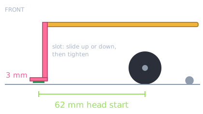
The two pink arms carry the cliff sensors out in front of the wheels. That head start is what lets Dusty stop in time.
You need
Both sensor arms (Batch 3)2 QTR-1A sensors and the bag of pins that came with them2 × M2 × 8 and 2 × M2 × 6, 4 nuts6 female-to-female jumper wires: 2 red, 2 black, 1 yellow, 1 greenSoldering iron and solder (grown-up)Tape or a scrap of foamFlush cutters2 US pennies
The sensor sees the edge 62 mm before the wheels get there.
a
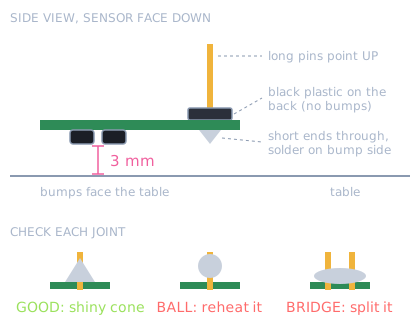
Find the header pins in the sensor bag and snap off two pieces of 3.
They are gold pins held in a black plastic strip. If it is a strip of 6, bend it at the middle notch with pliers and it snaps into two 3s. Use the straight pins, not the bent ones.
b
Push the short ends of one 3-pin piece through the three holes marked OUT, VIN and GND, from the back of the sensor.
The back is the side without the two tiny bumps. The black plastic sits flat against the back, and the short ends poke through on the bump side. The long pins point up when the sensor faces the table.
c
Hold it so it cannot tip while you solder.
Tape the plastic strip down, or push the long pins into a scrap of foam with the bump side facing up.
d
A grown-up solders the middle pin first.
Iron at about 330 to 350°C. Touch the tip to the pin and the gold pad together for about a second, feed a little solder into the joint (not onto the iron), take the solder away, then the iron. 2 to 3 seconds per joint: longer can cook the tiny sensor.
e
Check the pins stand straight up, then solder the two outside pins.
Tilted? Reheat the middle joint and nudge the strip straight while the solder is melted.
f
Check every joint.
Good is a small shiny cone around the pin. A round ball sitting on top needs reheating. Solder joining two pins is a bridge: drag the hot tip between them to split it. Nothing may stick out lower than the two bumps, or the sensor cannot sit at 3 mm. Snip a long pin end with flush cutters.
g
Do the second sensor the same way.
h
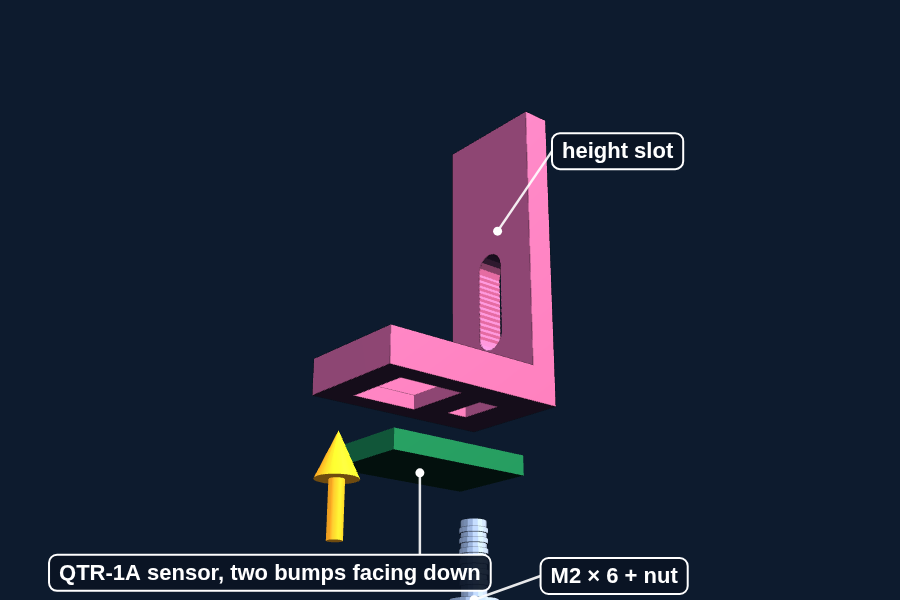
Put a sensor face down in the foot of each arm, and hold it with an M2 × 6 screw and nut.
The two tiny bumps must look down through the window.
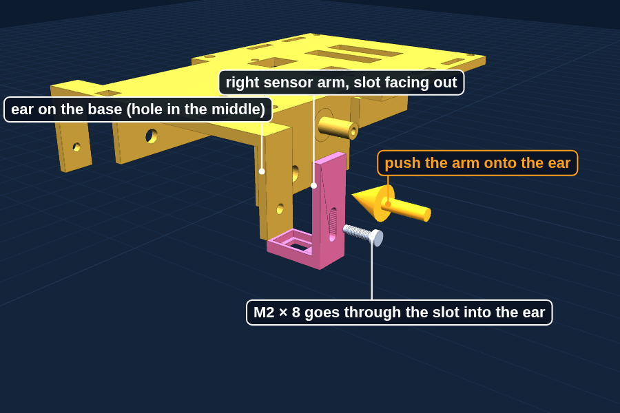
i
Hold the right arm against the outside of the right ear at the front of the base. The left arm, with the extra pad, goes on the left.
j
Push an M2 × 8 screw through the slot and the ear, and add a nut on the inside.
Snug, not tight yet.
k
Set Dusty on the table. Slide each arm until the sensor is 3 mm above the table, then tighten.
Two US pennies stacked are almost exactly 3 mm. Slide them under the sensor, push the arm down onto them, tighten, pull the pennies out.
l
Pick off anything stuck on the moto:bit SENSOR pins.
The board ships with its pins pushed into black foam, and bits can stay behind. Foam stops the plugs from going on, and it leaks a little electricity between pins, which throws off the sensor numbers.
m
Peel six jumpers off the ribbon: yellow, red and black for the left sensor; green, red and black for the right.
Red is always 3V3 and black is always GND. Each sensor gets its own signal color, so you can tell left from right at a glance.
n
Push one end of each left sensor jumper onto its pins: yellow on OUT, red on VIN, black on GND.
Push straight down until the black plastic sleeve stops. About 5 mm of pin disappears inside. A sleeve sitting crooked is only half on.
o
Switch the power off. Push the other ends onto the P0 column of the moto:bit: yellow on top, red in the middle, black on the bottom.
P0 is the left column of the first SENSOR block. Top is the row closest to the micro:bit slot.
p
Right sensor the same way on the P1 column: green on OUT and the top pin, red on VIN and the middle, black on GND and the bottom.
P1 is the right column of that same block. Leave the SERVO block alone: its middle row is full battery power, not 3V3.
q
Twist each sensor’s three wires loosely together, fold the extra length, and tape it to the side of the deck.
The jumpers are 30 cm long and Dusty needs about 10. Keep the loops away from the wheels and the brush.
Once the sensors work, wrap tape around the three plugs at each end. Then they go on as one plug and can never get mixed up.
Why it works
How does a cliff sensor see?
One bump is a tiny infrared light, the other is a light detector. Infrared is just past red, so your eyes cannot see it, but a phone camera can. Try it.
On the table, the light bounces straight back into the detector. Past the edge, it shines into empty space and almost nothing comes back.
Why it works
Why 3 mm?
This sensor sees best at about 3 mm and gets unreliable past 6 mm. The slot lets you set the height exactly, and set it again if an arm gets bumped.
You are done when
Both sensors sit 3 mm above the table, both arms are tight, and each sensor’s three wires are on its own column: left on P0, right on P1.
7
Step 7: Teach Dusty about edges
About 1.5 hours
The big one. By the end of this step Dusty stops itself at the edge of a real table, and you have the numbers written down to prove it.
You need
Laptop and ClaudeYour dusty-spec.txtNotebookWhite paper, a black placematA low table and a cushion for the floor
a
Check the sensor wires: left sensor on P0, right sensor on P1.
b
Run test T4 and write down the numbers.
On the table and held over the edge, for each sensor. Try white paper, bare wood and a black placemat. Table and edge should be far apart: maybe 200 on the table and 900 over the edge.
c
Put your numbers in the spec, then run test T5, the loop timer.
It tells you how often Dusty checks for the edge. The cliff math needs that number.
d
Ask Claude for test T6, the edge program. The logic below is what it has to do.
The rules are already in your spec. Your prompt only has to say which ones this program uses.
e
Before you flash it, switch MakeCode to Blocks and find each line of the logic below.
Find the thresholds, the check inside forever, and every pause. If you cannot explain a block, ask Claude about it before you run it.
f
Test on a low table. Twenty approaches: ten straight on, five at an angle, five into a corner.
g
Write down every single run in a notebook.
Twenty out of twenty, or keep fixing. Tell Claude exactly what happened on the runs that failed.
h
Then spring the trap in T5b.
It shows how code that looks fine can make Dusty notice the edge too late.
The logic, in plain steps · Claude writes the real code: find each of these in it before you flash
on startRuns once. Dusty sits still on the table.
turn motors ON
pause 1000 msTime to take your hand away
set leftTable to analog read P0, rightTable to analog read P1
set each threshold to its table reading + 200Much bigger than the table means no table
show icon: yesReady
on button A pressedGo
set driving to true
foreverThe main loop, at least 25 times a second
if driving and (P0 > left threshold or P1 > right threshold) then
stop both motors
drive backward 400 ms
spin for pick random 300 to 900 ms
else if driving
both motors FORWARD at 40
T4Test program: Sensor numbers
Checks: What each cliff sensor reads on the table and over the edge
1 · Write down first
Will the number be bigger on the table or over the edge? Which surface will be hardest?
2 · Ask Claude
Read dusty-spec.txt. Write test program T4 Sensor Numbers. No motors, no sounds. Button A shows the left sensor number. Button B shows the right. Also send both numbers to the laptop 10 times a second with serial write value, named left and right, so MakeCode can graph them. Explain every line.
3 · Read it, flash it, run it. It passes when
Table and edge numbers are far apart for both sensors on every surface. All of them go in the spec. With the cable in and paired, click Show console Device in MakeCode and watch the line jump as you slide Dusty off the edge by hand.
T5Test program: Loop timer
Checks: How many times a second Dusty checks for the edge
1 · Write down first
How many loops per second? The spec needs at least 25.
2 · Ask Claude
Read dusty-spec.txt. Write test program T5 Loop Timer. No motors. In the forever loop, read both cliff sensors and the whisker pin the way a real edge program would, and count each trip through the loop. Every second, save the count and start again from 0. Button A shows the last count. Explain every line.
3 · Read it, flash it, run it. It passes when
25 or more. Write the number in the spec. 25 a second means Dusty checks at least every 40 ms. At 70 mm per second that is under 3 mm of travel between checks.
T5bTest program: The trap
Checks: That code can look right and still be dangerous
1 · Write down first
Will the loop count change? By how much?
2 · Ask Claude
Add a happy face to T5 that shows the whole time the loop is running.
3 · Read it, flash it, run it. It passes when
Watch the count drop to about 1 or 2 a second: showing a picture makes the micro:bit wait more than half a second. Do the math: 0.6 s × 70 mm per second is 42 mm before Dusty even notices the edge, most of the 62 mm head start. At full speed, about 180 mm per second, that is 108 mm: off the table. If Claude warns you about spec rule 2 instead, that is the spec doing its job. Tell it this is an experiment, then change it back afterward.
T6Test program: Edge stop
Checks: Dusty stops and turns away at every edge
1 · Write down first
Which approach will be hardest: straight on, at an angle, or into a corner? Why?
2 · Ask Claude
Read dusty-spec.txt. Write test program T6 Edge Stop. Follow spec rules 1 to 7, but only button A (start driving) and A+B (stop) for now: no Spot Clean yet. Explain every line.
3 · Read it, flash it, run it. It passes when
20 out of 20: ten straight on, five at an angle, five into a corner, every run written in the notebook.
Why it works
What does "analog" mean?
Some questions have two answers: is the button pressed, yes or no. That is digital.
Other questions have a whole range of answers: how much light came back? That is analog. The micro:bit turns it into a number from 0 to 1023.
Analog is better here, because you get to pick where the line falls. Picking that line on the actual table you are using is what calibration means.
Why it works
Why calibrate at all?
A white tablecloth might read 200. Dark wood might read 650. If you hard-coded "over 500 means cliff", Dusty would refuse to move on the dark table.
So Dusty looks at whatever surface it is sitting on and decides for itself what normal looks like. Same code, any table. That idea is worth explaining to a judge.
Careful: Test on a low table first, and put a cushion on the floor. Your first few runs will have bugs, and a bug here means the robot drives off the edge.
You are done when
Twenty approaches out of twenty end with Dusty stopping and turning away, written down in the notebook.
8
Step 8: Add the whisker
About 30 minutes
A second way to notice the edge that works in a completely different way, so the two cannot fail for the same reason.
You need
Whisker switch2 × M2 × 10 with nuts1 blue and 1 black jumper wireScissors or wire strippersHeat shrink tube or electrical tapeSoldering (grown-up)
It is not looking, it is touching. A dark table cannot fool it.
a
Cut the blue and the black jumper about 10 cm from one plug.
Keep the pieces that still have a plug on the end. The plug is what pushes onto the moto:bit pin.
b
Strip about 3 mm of plastic off each cut end and twist the thin wires inside together.
A grown-up tins them: a little solder on the bare wire so the strands stay together.
c
Slide a short piece of heat shrink onto each wire before soldering.
Once the wire is soldered on, the tube cannot go on from the other end. Tape works if there is no heat shrink.
d
A grown-up solders blue to the NO tab and black to the C tab. NC stays empty.
The letters are molded into the plastic next to each tab. Hook the bare wire through the hole in the tab, then solder. Do this before the switch is screwed on, so the heat cannot soften the arm. C is common, NO is normally open.
e
Slide the heat shrink over each joint and shrink it.
A hair dryer or the side of the iron works. It stops the two tabs from touching.
f
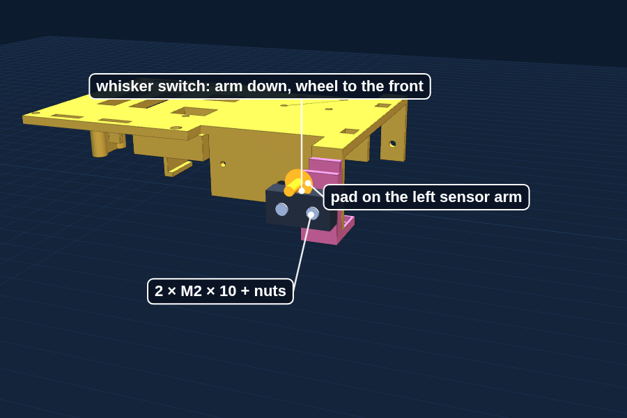
Screw the switch to the pad on the left sensor arm with two M2 × 10 screws and nuts.
Arm pointing down, little wheel toward the front.
g
Set Dusty on the table. The wheel should rest on the table and push the arm in with a click.
No click? Loosen the arm slot and lower it a little.
h
Switch off. Plug the wires onto the P2 column: blue (NO) on top, black (C) on the bottom. The middle pin stays empty.
P2 is the left column of the second SENSOR block, just right of P0 and P1. Same picture as Step 6.
i
Run test T7 to check the switch, then ask Claude to add the whisker to your edge program.
T7 needs no motors. The whisker rule is already in your spec: 1 on P2 means stop.
j
Test it with both infrared sensors covered by tape.
Only the whisker is working now. Does Dusty still stop?
T7Test program: Whisker check
Checks: The whisker switch reads 0 on the table and 1 at the edge
1 · Write down first
What should the LEDs show when you lift Dusty off the table? When a whisker wire comes loose?
2 · Ask Claude
Read dusty-spec.txt. Write test program T7 Whisker. No motors. Set pull pin P2 to up. In forever, show a check mark when P2 reads 0 and an X when it reads 1. Explain every line.
3 · Read it, flash it, run it. It passes when
Check mark on the table. X when you lift Dusty. X when you pull a whisker wire off: the safe way to fail. Then ask Claude to add the whisker to T6 as rule 5 says, and run the taped-sensor test below.
Why it works
Why two of everything?
The infrared sensors can be fooled by a black placemat. The whisker cannot, because it touches instead of looking. Engineers call this redundancy: two systems that fail for different reasons.
When a judge asks "what if the sensor is wrong?", this is the answer.
You are done when
With the infrared sensors taped over, Dusty still stops at the edge using only the whisker.
4
Chapter 4
Batch 4: Brush drive
During the week before weekend 3 · About 1 hour · 13.5 g
1 · Print
On the plate
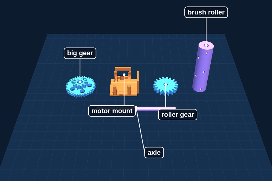
Brush motor mount, big gear, roller gear, brush roller (standing up), axle (lying flat)
Everything for the brush except the small pieces from Batch 1. Printed ahead so there is time to fix a gear before the brush weekend.
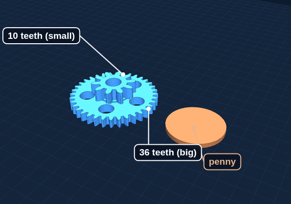
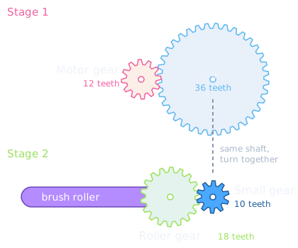
1Look at the plate picture. The motor gear has 12 teeth and the big gear has 36. How many times does the motor turn for one turn of the big gear?Answer: 36 divided by 12 is 3. Slower, but three times stronger.
2The small gear has 10 teeth and the roller gear has 18. Multiply both steps together.Answer: 3 times 1.8 is 5.4. The brush turns 5.4 times slower than the motor.
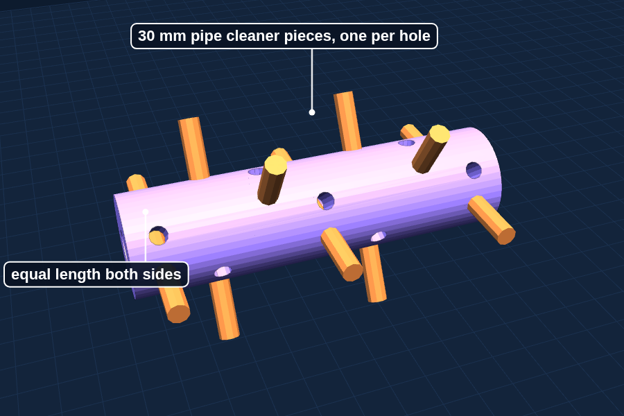
3Cut about 20 pipe cleaner pieces, each 30 mm long.Watch the first layers of the roller while you cut. It is tall and thin, and it must stick well.
2 · Know your parts
Every piece from this plate, next to a penny for size. The colors in the pictures only tell the parts apart: yours come out the color of your filament.
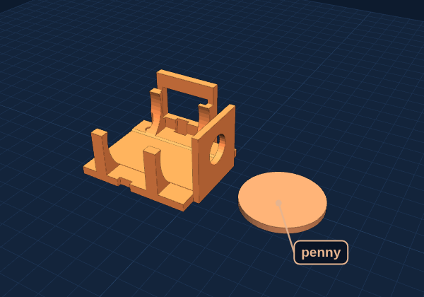
Motor mount
Open box, 29 × 26 × 17 mm, with a round opening shaped to fit the motor.
Job: Holds the 130 brush motor and the brush on/off switch. The two dowels from Batch 1 line it up on the base.
Goes to: BATCH 4 cup, Build Step 9
Big gear
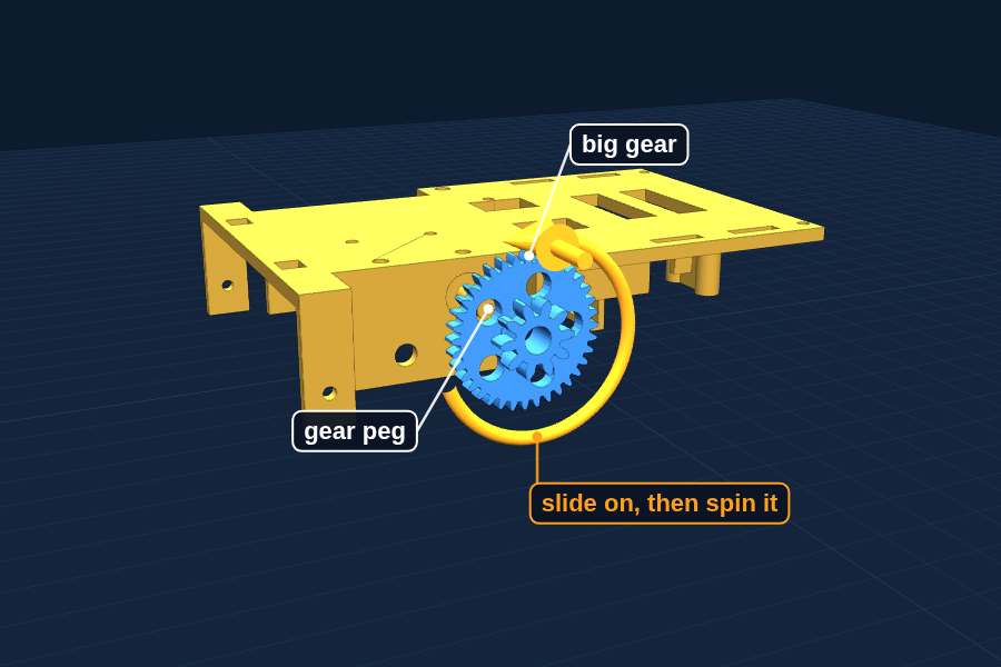
Two gears joined together: a big one with 36 teeth and a small one with 10 teeth, and five round holes.
Job: Spins on the gear peg. It slows the motor down and makes it stronger.
Goes to: BATCH 4 cup, Build Step 9
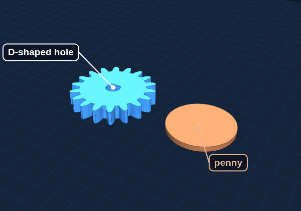
Roller gear
Gear with 18 teeth, 25 mm across. Its hole has a flat side, like a D.
Job: Sits on the end of the axle and turns the brush roller.
Goes to: BATCH 4 cup, Build Step 9
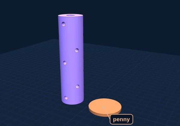
Brush roller
Tube, 52 mm long and 14 mm thick, with 7 small holes going across it.
Job: Pipe cleaner pieces go through the holes to make the brush.
Goes to: BATCH 4 cup, Build Step 9
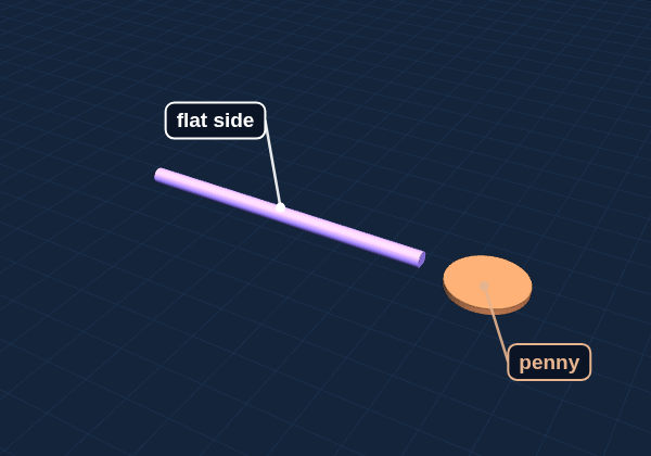
Axle
Long thin rod, 75 mm, with one flat side.
Job: Goes through the roller and the roller gear so they turn together.
Goes to: BATCH 4 cup, Build Step 9
3 · Clean up and check
When it is done printing
1
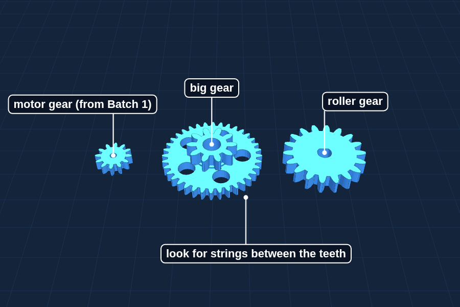
Check the gear teeth are clean.
The gears print with no brim, so there is nothing to trim. If a tooth has a stray string, a grown-up cleans it with a hobby knife.
2
Slide the axle through the roller, then put the roller gear on the end.
Line up the flat side of the axle with the flat inside each part. They should slide on, not wobble.
3
Slide the big gear onto the gear peg on the base and spin it.
It should spin freely. If it drags, sand the inside of the hole a little.
4
Hold the motor gear from Batch 1 against the big gear and turn it.
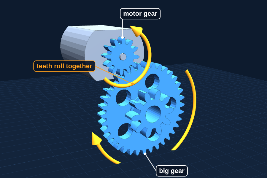
The teeth should roll together without jamming.
Ready to move on when
The axle fits and the big gear spins freely. Everything waits in the BATCH 4 cup for Step 9.
4 · Build
This batch unlocks Steps 9.
9
Step 9: Build the brush and the gears
About 2 hours
Now Dusty earns its name. The brush motor spins far too fast for a brush, so three printed gears slow it down before it reaches the roller.
You need
Batch 4 parts and the BATCH 4 cup (motor gear, washer, collar, 2 dowels)130 motor, rocker switchPipe cleaners, 1 small zip tie (plus a spare), screw-terminal jack2 × M2 × 8, 1 × M2 × 6Scissors or flush cutters, a folded towelSuperglue (grown-up)
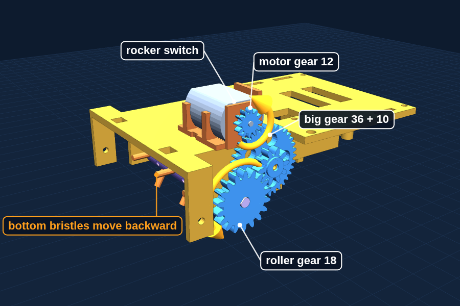
The brush gear train, seen from the right side of the robot.
a
Cut pipe cleaners into pieces about 30 mm long and push one through each hole in the roller.
Center each piece so the same length sticks out both sides.
b
Check the motor has no gear on its shaft yet.
The gear will not fit through the hole in the right-hand wall of the mount, so it goes on after the motor is in. If the gear from the Batch 1 test is still on, wiggle it straight off. If it cracks, a grown-up prints a new one (dusty-pinion-revA5.stl, a few minutes).
c
Snap the rocker switch into the square hole in the back wall of the motor mount.
Easier now, before anything else is in the way.
d
Thread the zip tie before the motor goes in. Push its tail down through one slot in the floor of the mount, along underneath the floor, and up through the slot on the other side of the curved motor cradles. Leave a big loose loop over the top.
The two slots are on either side of the motor cradles, about halfway along. The flat band runs under the floor and the square head stays on top, beside the motor, never underneath.
e
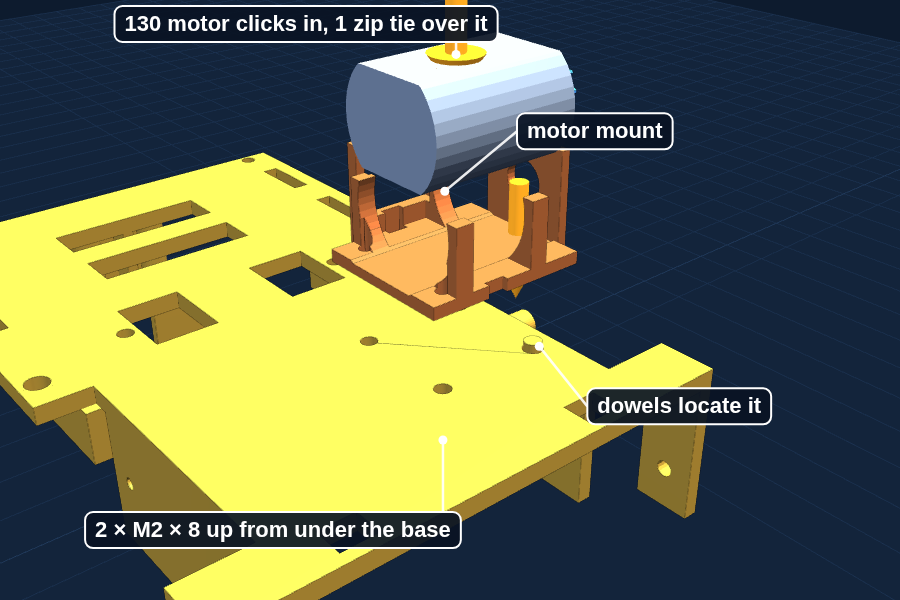
Put the motor into the mount, through the loop, shaft pointing to the right side. Tip the shaft end in first so the shaft and the round collar around it go into the hole in the right-hand wall, then press the back end down until it clicks into the two curved cradles.
The flat sides of the motor face up and down. The collar sits in the hole, and the back of the motor rests in the rear cradle.
f
Pull the zip tie tight over the motor and snip off the tail.
Snug so the motor cannot lift or slide backward. Cut the tail close to the head so it cannot touch the gears.
g
Press the motor gear onto the shaft where it sticks out of the right-hand wall.
Hold the back of the motor with your other thumb so it does not slide back. Stop when the shaft tip just peeks through the gear and a paper-thin gap is left between the gear and the wall. If it slips, a grown-up adds a tiny drop of superglue, kept off the teeth.
h
Push the two dowels into the two small holes in the top of the base, to the right of center near the front.
They stick up a little over 1 mm. They are tiny: use the pliers, and do this over the towel.
i
Set the motor mount on the dowels so they go into the two holes under its right edge. The mount sits flat, gear on the right.
The dowels put the motor gear exactly where the big gear will be. If the mount rocks, a dowel is not in its hole.
j
Lay Dusty on its side on the folded towel. Hold the mount down and drive two M2 × 8 screws up from under the base, through the two holes just right of center near the front, into the mount.
Do this now, before the roller goes in: the roller covers both holes. Turn each screw a little at a time, back and forth, so the mount pulls down evenly. The zip tie band under the mount makes a tiny bump; that is expected. Snug, then stop.
k
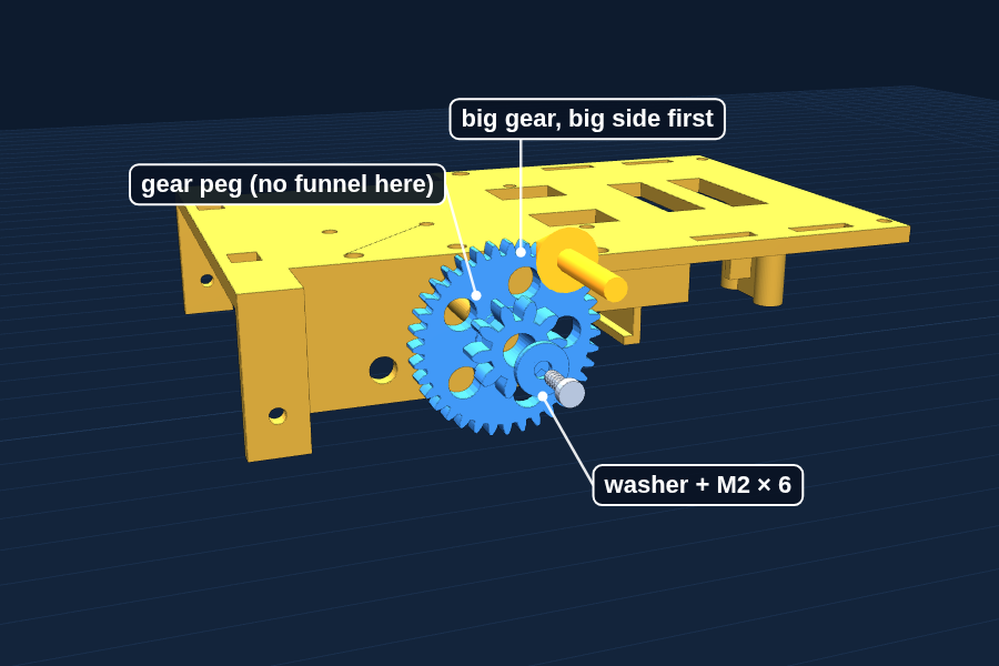
Slide the big gear onto the peg on the right side plate, big side first. Add the washer and an M2 × 6 screw into the end of the peg.
The gear must spin freely. If it drags, back the screw off a quarter turn. Turn it slowly by hand: the motor gear should turn with it all the way round without catching or clicking. If it catches, check the mount sits flat on its dowels.
l
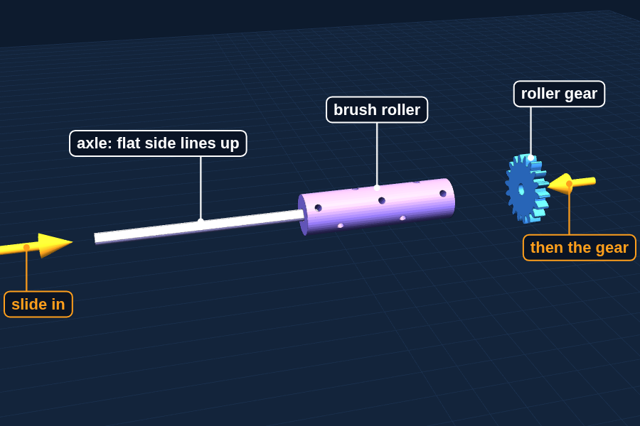
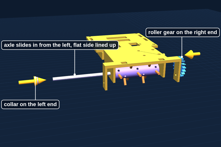
Slide the axle in from the left side plate, through the roller, and out the right side plate. Push the roller gear onto the right end and the collar onto the left end.
The flat side of the axle lines up with the flat inside the roller and the roller gear.
m
A grown-up wires the brush: the splitter’s second end to its screw-terminal jack, then through the rocker switch to the motor tabs.
Power off while wiring.
n
Switch on and check which way the roller spins.
The bristles at the bottom must move backward, toward the tray. Wrong way? Power off, swap the two wires on the motor tabs.
Try it: put a marker dot on one tooth of the motor gear and one on the roller gear. Turn the roller slowly by hand and count how many times the motor gear goes around. You should count about five and a half.
Why it works
How the gears slow the brush down
When two gears touch, their teeth pass each other one for one. The motor gear has 12 teeth. The big gear has 36. So the motor gear goes around 3 times to push the big gear around once.
The big gear has a small 10-tooth gear stuck to it, so they turn together. That small gear drives the 18-tooth roller gear. 18 ÷ 10 is 1.8, so it slows down again. The two slow-downs multiply: 3 × 1.8 = 5.4 times slower.
Why it works
What do you get for going slower?
Strength. Engineers call turning strength torque. Gearing down by 5.4 gives the roller about 5.4 times the turning strength, minus a little lost to friction. That lets fuzzy bristles push through cereal without stalling.
A plain 130 motor spins roughly 8,000 to 10,000 times a minute. Divided by 5.4, the roller turns about 1,500 to 1,800 times a minute.
Careful: Fingers, hair and sleeves stay away from the gears and the brush while they spin. Switch the brush off before touching anything near the front.
You are done when
The brush switch starts the roller, all three gears turn smoothly, and the bristles at the bottom move backward toward the tray.
5
Chapter 5
Batch 5: Crumb tray
After Batch 4 · About 15 minutes · 7 g
1 · Print
On the plate
Crumb tray
Last, because it sits right behind the brush. If the brush needed changes, the tray can change too.
1Put a small bowl on the kitchen scale and press the zero (tare) button.Now the scale only counts what you add, not the bowl.
2Crush some cereal and weigh out exactly 5 grams for the sweep test.Saying "Dusty picked up 3.8 of 5 grams" is a measurement. "It cleans pretty well" is an opinion.
2 · Know your parts
Every piece from this plate, next to a penny for size. The colors in the pictures only tell the parts apart: yours come out the color of your filament.
Crumb tray
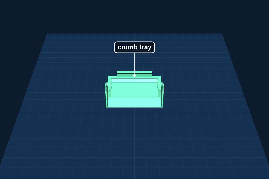
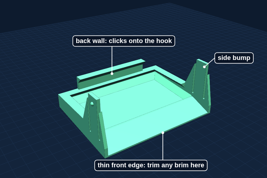
Shallow tray, 57 × 42 mm, with a thin front edge, a taller back wall and a tab on each side.
Job: Catches the crumbs the brush flicks back.
Goes to: Build Step 10
3 · Clean up and check
When it is done printing
1
Check the bottom of the tray is flat and the front edge is thin and clean.
The tray prints tipped back a little so its sloped bottom lies flat on the bed. Trim any brim off the front edge, because that edge rides on the table.
2
Turn Dusty upside down on a towel and press the tray on until the back clicks.
The two side bumps click too. To take it off, push the back wall forward a little.
Ready to move on when
All 21 pieces printed. Dusty is complete.
4 · Build
This batch unlocks Steps 10 to 11.
10
Step 10: Slide in the tray and test the sweep
About 1 hour
The tray catches what the brush flicks. It snaps in from underneath and pops back out, so you can weigh what Dusty picked up.
You need
Crumb tray (Batch 5)Kitchen scale5 g of crushed cereal
a
Check the tray: flat bottom, thin clean front edge.
Trim any brim off the front edge, because that edge rides on the table.
b
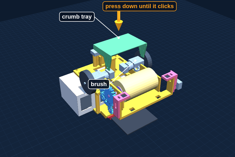
Turn Dusty upside down on a towel. Set the tray in place with the ramp toward the brush, and press until the back clicks over the hook and the two side bumps click in.
To take it out: push the back wall of the tray a little toward the front so it slips off the hook, and lift.
c
Set Dusty on the table and look from the side. The bristles should just touch the table.
Pressed hard, the brush acts like a brake. Too high, it misses crumbs. Trim the pipe cleaners to adjust.
d
Check the tray from the side: the front edge touches the table, with a thin gap under the back.
If the front edge scrapes hard, sand it a little.
e
Weigh 5 grams of crushed cereal, sprinkle it in a strip, and let Dusty drive through it with the brush on.
f
Pop the tray out and weigh what is inside. Write down the number.
Do this three times and take the average.
Why it works
How the tray keeps crumbs in
The front of the tray is a ramp that climbs to a little ridge, then drops. Crumbs flicked over the ridge cannot roll back out. It works like a one-way door. The corners inside are sloped so crumbs slide to the middle, and a small lip along the top catches bouncers.
Why it works
Why the bottom slopes
A tray lying flat would rub along its whole bottom, and the motors would waste their push fighting that friction. So only the thin front edge touches the table. The bottom tilts up, and the back floats 2.5 mm above the table. The tray hangs from the hook and the side bumps.
Why it works
Why weigh it?
"Dusty cleans pretty well" is an opinion. "Dusty picked up 3.8 grams out of 5, which is 76 percent" is a measurement. Science runs on measurements.
Careful: Keep crumbs off the sensors. If the brush throws crumbs forward onto a sensor, it goes blind. Check the spin direction, and wipe the sensor faces before each test.
You are done when
You can say a real number out loud: "Dusty picked up __ grams out of 5."
11
Step 11: Two brains, then run the experiment
A whole weekend
The robot is finished. This weekend turns it into a science project, and this is what the display board is really about.
You need
Charged power bankRuler taped along the table edgeNotebookMasking tape for a 1 foot square5 g of crushed cerealPhone for slow-motion video
Same robot, two different ideas. Race them and see which wins.
a
Run test T8: your edge program becomes the main program, random bounce on A and Spot Clean on B.
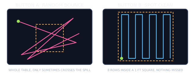
Spot Clean sweeps a 1 foot square in front of Dusty in rows, like mowing a lawn. The logic below is what it has to do. The cliff sensors still work the whole time.
b
Tape a 1 foot (30 cm) square on the table. Put Dusty at the bottom left corner, facing into the square, and press B.
Adjust the row time until Dusty just reaches the far tape, and the turn time until each turn is square.
c
Load test T9 and run the speed experiment at four speeds: 25, 50, 75 and 100. Twenty runs at each.
Touch the gold logo to change speed. Cushion on the floor anyway.
d
For every run, write down how far the sensor went past the edge before Dusty stopped, in millimeters, and whether it fell.
A ruler along the edge makes it easy. Slow-motion video makes it exact.
e
Make the first chart: speed along the bottom, stopping distance up the side.
f
Spill race: 5 g of cereal in the square. Press B and time Spot Clean until it stops. Weigh the tray.
g
Same 5 g, same square. Press A and stop random bounce after the same time. Weigh the tray.
Same time, same crumbs, same spot. Only the pattern changes.
h
Do three tries of each pattern and make the second chart: grams picked up by each pattern.
If there is time, try white paper, bare wood and a black placemat.
The logic, in plain steps · Claude writes the real code: find each of these in it before you flash
on button B pressedSpot Clean
set lane to 0
repeat 8 times8 rows about 4 cm apart fill the 30 cm square
driveFor 4400 msOne row: 30 cm at 40%. driveFor checks the cliff sensors every 40 ms
if lane is even: turn RIGHT 90, otherwise turn LEFT 90
driveFor 570 msSlide over about 4 cm
turn the same way 90 againNow Dusty faces back across the square, one row over
change lane by 1
stop both motorsDone. Pop out the tray and weigh it
T8Test program: Main program
Checks: Both cleaning patterns work and the cliff checks never stop
1 · Write down first
Inside the taped square, where will Spot Clean miss? What happens if the square is near the table edge?
2 · Ask Claude
Read dusty-spec.txt. Turn my edge program into the main program Dusty v1: random bounce on A, Spot Clean on B exactly as spec rule 8 says, A+B stops. Keep every safety rule. Explain every line, and tell me what changed from T6.
3 · Read it, flash it, run it. It passes when
Spot Clean ends at the far tape with square turns, and with the square taped against the table edge, Dusty still stops at the edge. Then run T5 on this program: still 25 loops a second or more.
T9Test program: Speed picker
Checks: You can set the four experiment speeds without changing the code
1 · Write down first
Your stopping distance at each speed, before you measure any of them.
2 · Ask Claude
Read dusty-spec.txt. Copy Dusty v1 into test program T9 Speed Picker, only for the experiment. Touching the logo steps the speed 25, 50, 75, 100 and back to 25, and shows the number while Dusty is stopped. Button A drives straight at that speed with the edge stop. Everything else stays the same. Explain what you changed.
3 · Read it, flash it, run it. It passes when
The number shown matches the speed Dusty drives, and it still stops at the edge at 25. Then run the experiment.
Why it works
Why 8 rows, 4 cm apart?
The brush is 52 mm wide. With rows 40 mm apart, each row overlaps the last by 12 mm, so no stripe gets missed. A foot is about 305 mm, and 305 ÷ 40 is about 8 rows.
Why it works
What should happen?
Faster means more distance to stop. Prediction: double the speed and the stopping distance more than doubles, because a faster robot has more to slow down and covers more ground while the code reacts.
Dusty has a 62 mm head start. If your chart climbs toward 62, draw the line forward and predict the speed where Dusty would fall. Put that number in big type on the board.
You are done when
A filled-in data table and two charts made from your own numbers: stopping distance by speed, and grams picked up by pattern.
When it misbehaves
Fixing it
What you see
Most likely cause
What to do
Nothing happens at all
Power
Switch on? Tapped the power bank button? Plugs pushed fully in? Charge the power bank.
micro:bit lights up, motors do nothing
Motors not turned on
Find turn motors ON in on start (flip to Blocks), and check the moto:bit switch is on RUN.
Drives in a curve
One motor slower
Check both wheels are fully on. Then write the drift in the spec and ask Claude to slow the faster side by a few percent.
One wheel goes backward
Wires swapped
Write invert yes for that motor in the spec and ask Claude to add it. No rewiring.
A wheel does not turn at all
Wrong wire
Only red and white go to the motor terminal. Black is a turn-counter wire on these motors.
A motor will not sit flat on its pad
Old base file, or plug facing the wrong way
The plug must point into the square window. A base without windows is an old file: reprint Plate 2 from the current files.
A print lifted off the bed
First layer did not stick
Clean the bed, let it heat fully, try again. A glue stick helps.
A screw will not start
Hole too small
Check you printed the current files: the deck ends in revA7, every other part in revA5. Push firmly and turn slowly: the funnel should guide it.
A screw spins and will not tighten
Stripped plastic thread
Use the next longer screw, or a grown-up adds a drop of glue in the hole and waits.
A deck post wiggles in the base
Old base file
Post holes since Rev A.5 are 3.95 mm and snug. Reprint the base from the new files.
A part will not fit
Printed a little big
Sand or file the edge a little. Do not force it: PLA cracks.
Refuses to move, sensors fine
Dark surface
It thinks it is at a cliff. Recalibrate: switch Dusty off and on again, sitting still on that table.
Notices the edge late
Slow loop
Run T5 on your program. Anything that shows or scrolls on the LEDs inside forever slows the loop down.
Falls off despite the sensors
Arm moved or too fast
Re-check the 3 mm height, re-tighten the arms, lower the speed.
Gears click or skip
Big gear loose
Check the washer screw. The gear should spin freely but not wobble.
Brush motor hums, roller does not turn
Too much drag
Bristles too long or pressing too hard. Trim the pipe cleaners. Check nothing rubs the gears.
Motor gear slips on the shaft
Press fit too loose
A grown-up adds a tiny drop of superglue. Keep it off the other gears.
Crumbs fly forward
Brush spins the wrong way
Switch off, swap the two wires on the brush motor tabs.
Stops suddenly, micro:bit goes dark
Power bank empty or asleep
Tap the bank button. If nothing happens, charge it. Keep the brush on while driving so the bank stays awake.
micro:bit will not take the code
Cable
Many micro-USB cables only charge. Use one you know moves data. No MICROBIT drive on the laptop means the laptop cannot see it.
Download does nothing
Not paired
Click Download and follow the pair steps, or drag the .hex file from Downloads onto the MICROBIT drive.
Claude’s code shows red errors
Wrong tab or missing extension
Paste into JavaScript, not Blocks, and check the moto:bit extension is added. Paste the exact error back to Claude.
New version broke what worked
Too many changes at once
Go back to the last version that passed its test. Ask for one change, then test again.
Claude says it cannot do what you asked
A spec rule
Good. Read which rule it names. Change the request, or change the spec on purpose and write down why.
Say these like you mean them
Words to know
MicrocontrollerA tiny computer that does one job forever, using barely any power.
H-bridgeFour switches that let a motor spin either direction. Inside the moto:bit.
InfraredLight just past red that eyes cannot see. TV remotes use it.
PLAA plastic made from plants. The printer melts it and builds parts in layers.
LayerOne thin slice of a 3D print, 0.2 mm on Dusty.
BrimA thin one-layer ring printed around a part so it sticks to the bed. Peeled off afterward.
Fit checkA small test print that checks sizes before the big print.
Pilot holeA hole a bit smaller than the screw, so the screw cuts its own thread.
Lead-inA small funnel at the top of a hole that guides the screw in straight.
Change order (MOC)A written, approved change to a locked design, with the reason and the tests.
Gear ratioHow many turns in for one turn out. The brush gears are 5.4 to 1.
TorqueTurning strength. What gearing down gives you more of.
PWMFlicking power on and off very fast to make a motor run slower.
AnalogA measurement with a whole range of answers, not just yes or no.
CalibrationLetting the robot measure its own surroundings instead of guessing.
ThresholdThe line you draw in a measurement: above means cliff, below means table.
RedundancyTwo systems that fail for different reasons, so one catches what the other misses.
SpecThe written list of what a program must do and must never do. Short for specification.
PromptWhat you type to Claude. A good one is short, exact and asks for one job.
Test programA small program that checks one thing, with a pass or fail you decide before you run it.
FlashCopy a program onto the micro:bit so it stays there.
Loop timeHow long one trip through the forever loop takes. Shorter means Dusty sees the edge sooner.
BugA mistake in the code. Tests find bugs. Reading code only finds some of them.